Introducing RapidCHECK
The idea of RapidCHECK is to provide fast and automated analysis of CT images. Although the software works with three different types of phantom (the IQphan Phantom, the CT ACR 464 Phantom and the Advanced Electron Density (AED) Phantom), our application is AED only.
In principle, the AED 1467 is similar to our CIRS 062 with the important difference that the AED rods have drilled holes on one end, which allows pattern recognition in the software to read a code on the CT images. The code identifies the material of each rod. RapidCHECK auto-aligns the phantom, finds the Rod Identification Slice, determines the code of each rod, evaluates the HU in a certain 3D volume of interest, assigns the HU to a material and constructs HU-to-Electron-Density and HU-to-Mass-Density curves1.
(120kV curve in the "high" range up to titanium)
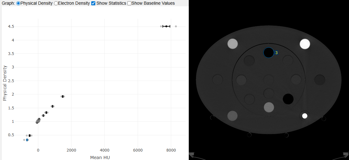
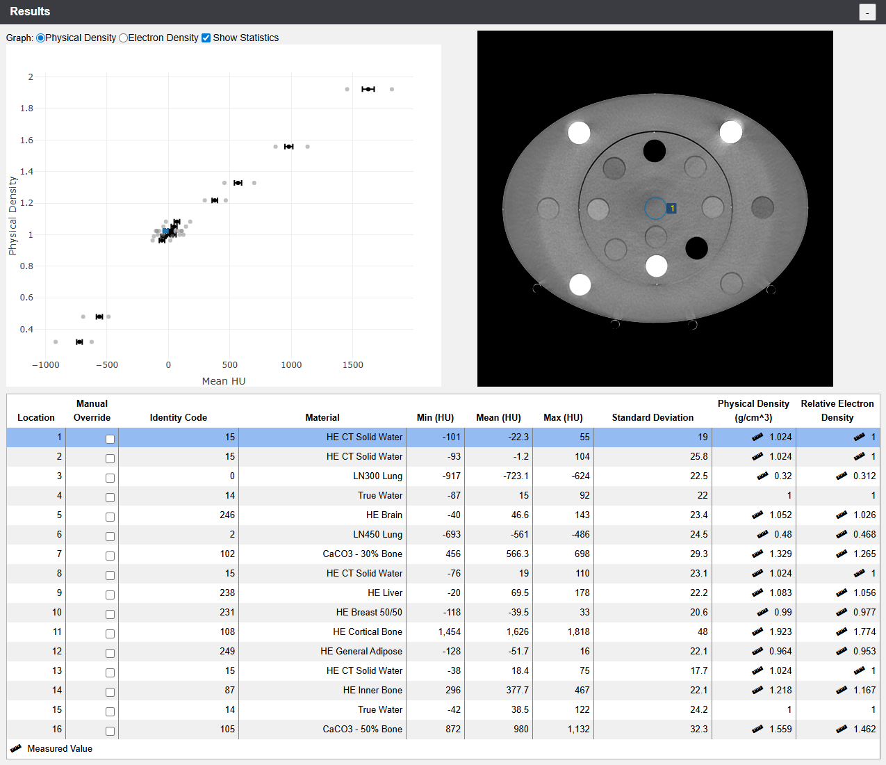
If one or more rods are not identified correctly during the analysis, the table view (see below) and the Image Registration offer ways to "assist the software". In this example, we selected the correct Identity Code for the material actually used in locations 1 and 3, because RapidCHECK had failed to identify the rods:
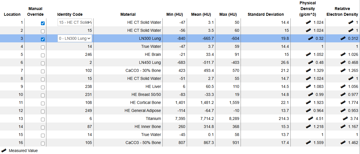
(120kV "high" results.)
The ruler icon nearby a value means that density values are taken from a calibration certificate. Otherwise, batch independent "nominal" values are used, which can be slightly different.
Location numbering in the AED is according to the following rules: 1 = center, 2 = halfway down, 3-10: inner circle (clockwise), 11-16: outer circle (clockwise):
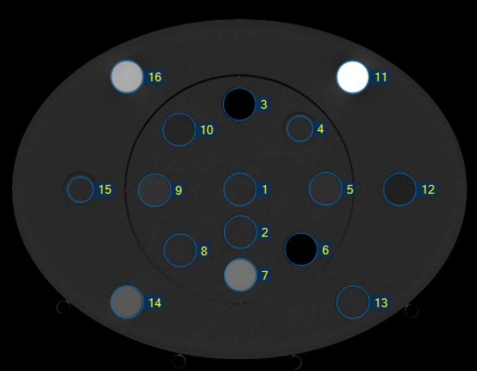
(Location numbering in the AED 1467 phantom.)
How We Use the Software
We started to use RapidCHECK first on our CT scanner (goOpenPro) and a little later on the TrueBeams (CBCT). It serves both the (occasional) creation of new calibration curves (after tube replacement etc.) and the regular verification of the constancy of measured HU values.
Machine: goOpenPro
For the constancy checks on the goOpenPro, we defined 16 kV-specific QA Tasks, eight in the "low" density range (up to Cortical Bone) and eight in the "high" range (up to titanium):
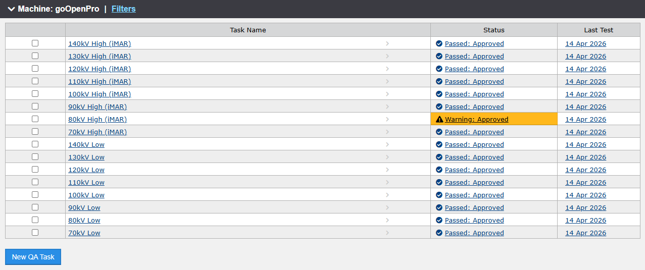
In the "high" configuration, the Solid Water rod in location 13 is replaced by the titanium rod. The scanner protocols also differ slightly: the iMAR metal artefact reduction is active in the "high" scans.
In each QA Task, the current Test compares HU values to an established Baseline. A test is considered passed if all values are within the specified limits. The orange warning in the "80kV High (iMAR)" test from April 14th resulted from a titanium value which is slightly higher than nominal:
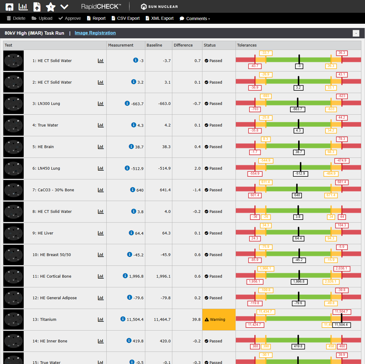
The single warning is mysterious, because the other tests passed without warning. Note that once a test result is approved, it can neither be changed nor deleted.
Two setups with eight energies each sound like a lot of work, both during the scan and the analysis. But it is not: on the goOpenPro, we defined two (Physics) Scan Protocols, for the "low" and "high" configuration. Each protocol comprises eight spiral scans. The user aquires a topogram, defines the start and stop positions for the spiral scan, copies this setting to the other seven scans, and presses Go. After eight scans, the room is entered once, one rod is swapped, and the procedure is repeated.
When the scanner has finished the reconstructions, all images are exported to Eclipse. From there, the images are exported as files, copied on a USB stick, transferred to the RapidCHECK laptop (reason: see Part 2), and analysed.
There are several options for creating output in RapidCHECK: PDF report, CSV export, XML export. For reporting of QA results, we generate PDFs (e.g., April 14, 2026 "low" scans: 70kV, 80kV, 90kV, 100kV, 110kV, 120kV, 130kV, 140kV, "high" scans: 70kV, 80kV, 90kV, 100kV, 110kV, 120kV, 130kV, 140kV).
Rod Identification
On the tip of each rod, several (between 3 and 13) holes are drilled (1 cm deep), which both define a coordinate system and a bit pattern, see below:
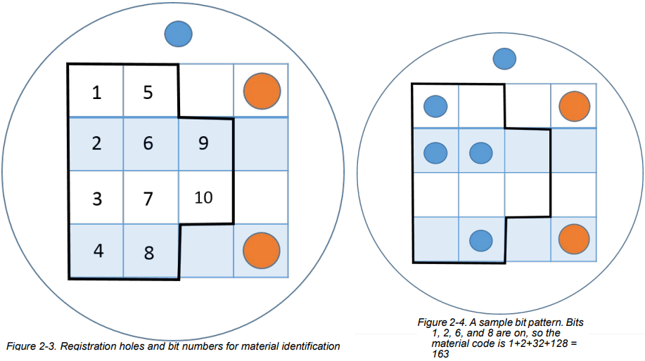
The resulting code is used to identify the rod material. Column 1 in the Rod Material Editor lists most of the codes:
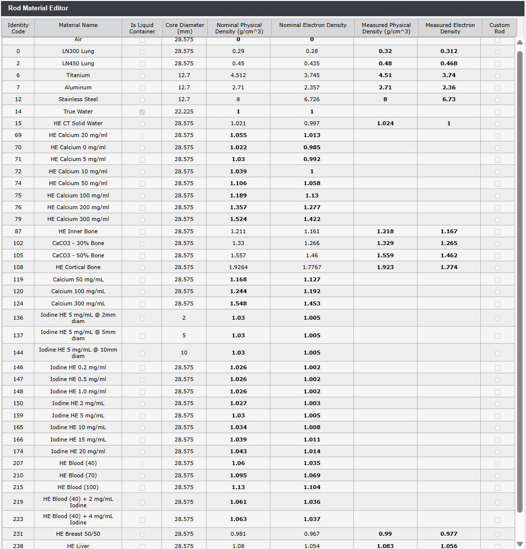
(Rod Material Editor. If "measured" values are not available, nominal densities are used.)
After the first few scans on the goOpenPro, we observed that the rods are not always identified correctly by the software. The rods which fail more often are either at certain locations (1, 2), have low density (LN300 Lung) or high density (108 - Cortical Bone).
This can be corrected, but it requires the user to be confident about the true material used at a certain location. One can either take a photo of the setup or use some other means to document the configuration. We adapted our paper form which we used for the CIRS pantom:
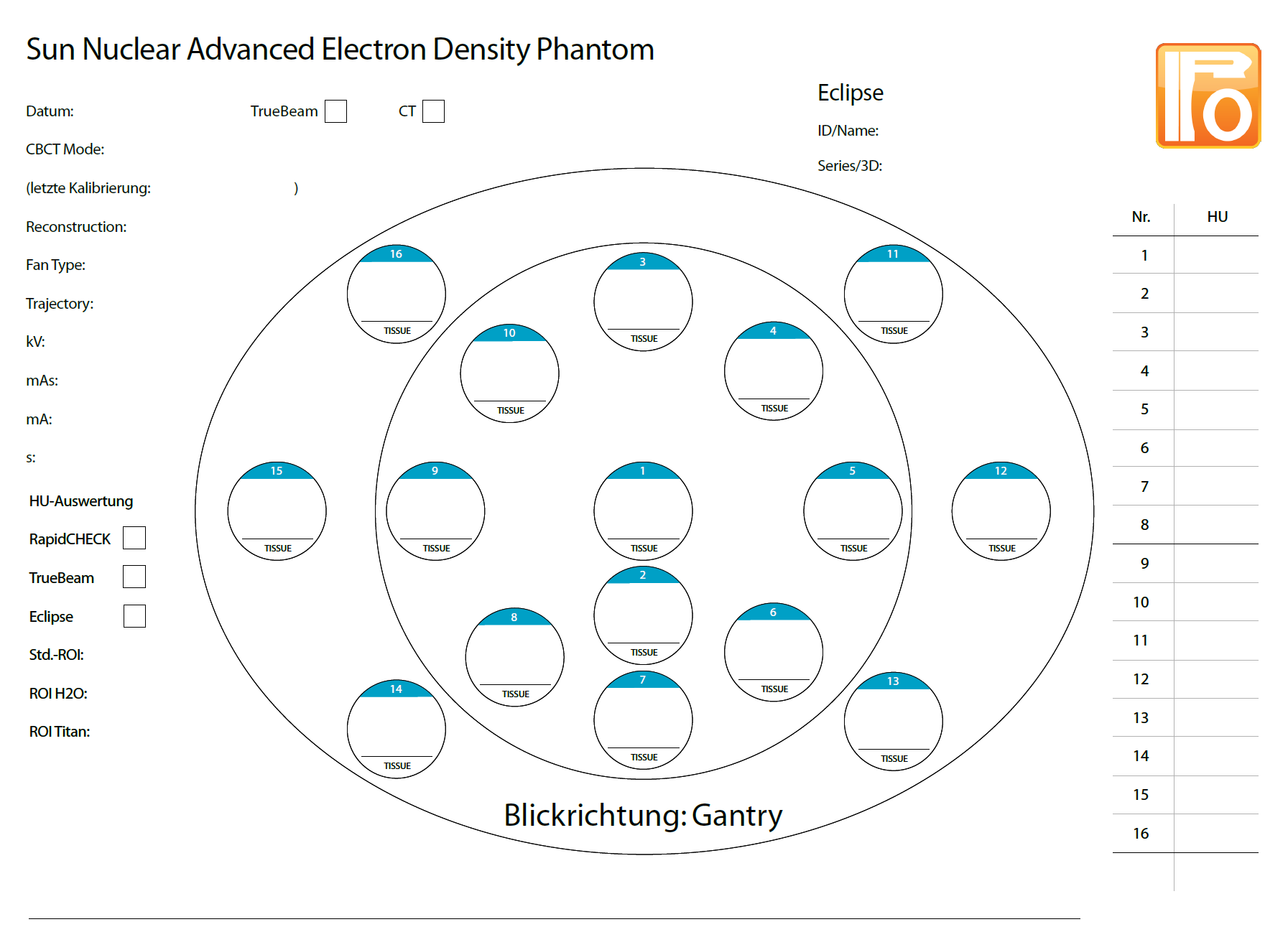
(Simple sheet for the documentation of the rod configuration.)
The reason why the identification sometimes fails is unclear. We suspect that on the CT, the ring artefacts play a role, especially on the phantom axis in location 1 (see next image).
In the image registration view, one can try other rod identification slices than the one determined by the software (here: slice 6), correct translational misalignments in steps of 1 mm or 0.1 mm, or one can set rotations:
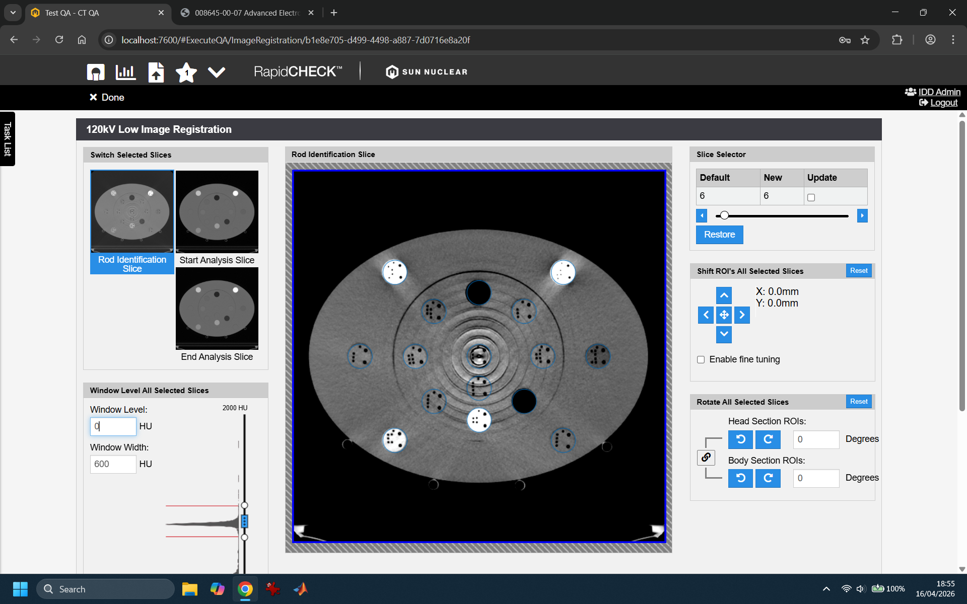
We also tried different slice thicknesses (1mm, 2mm), without effect. It sure is no simple image processing task to locate the coding holes, especially if the material density is low, like in the LN300 Lung rod: the density difference between the rod material itself and the drilled holes is minimal.
In any case, this is not a major problem, since most of the time, only 3 or 4 rods are affected, and the material assignment can be corrected.
We won't discuss the various trending possibilities here, because the number of scans performed so far is too small.
Comparing AED and CIRS
So far, we had used the CIRS 062 phantom for creating our calibration curves in Ecilpse. The current version, 18.1, uses calibration curves for 70 to 140 kV which are based on scans of the CIRS phantom.
When the resulting curves of CIRS and AED are compared, one has to consider that the rod materials and consequently the density sampling points are not matching exactly2:
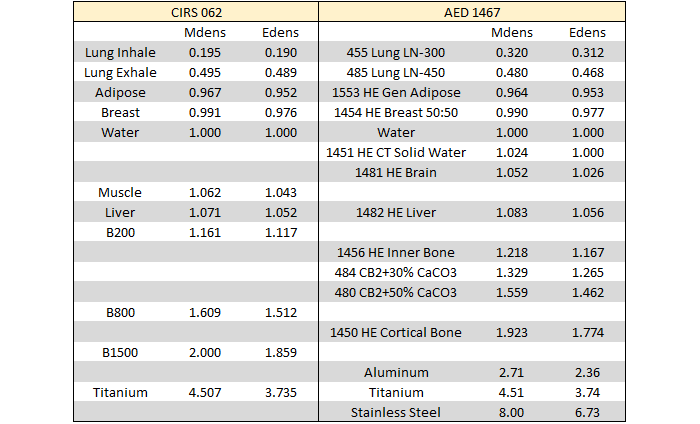
(Comparison of materials and density sampling points. The AED values are taken from our certificate.)
As a consequence, plotting stepwise linear calibration curves of AED and CIRS on top of each other gives a good impression of the agreement; however, for plotting differences (either at certain density or HU values) the curves would have to be resampled first.
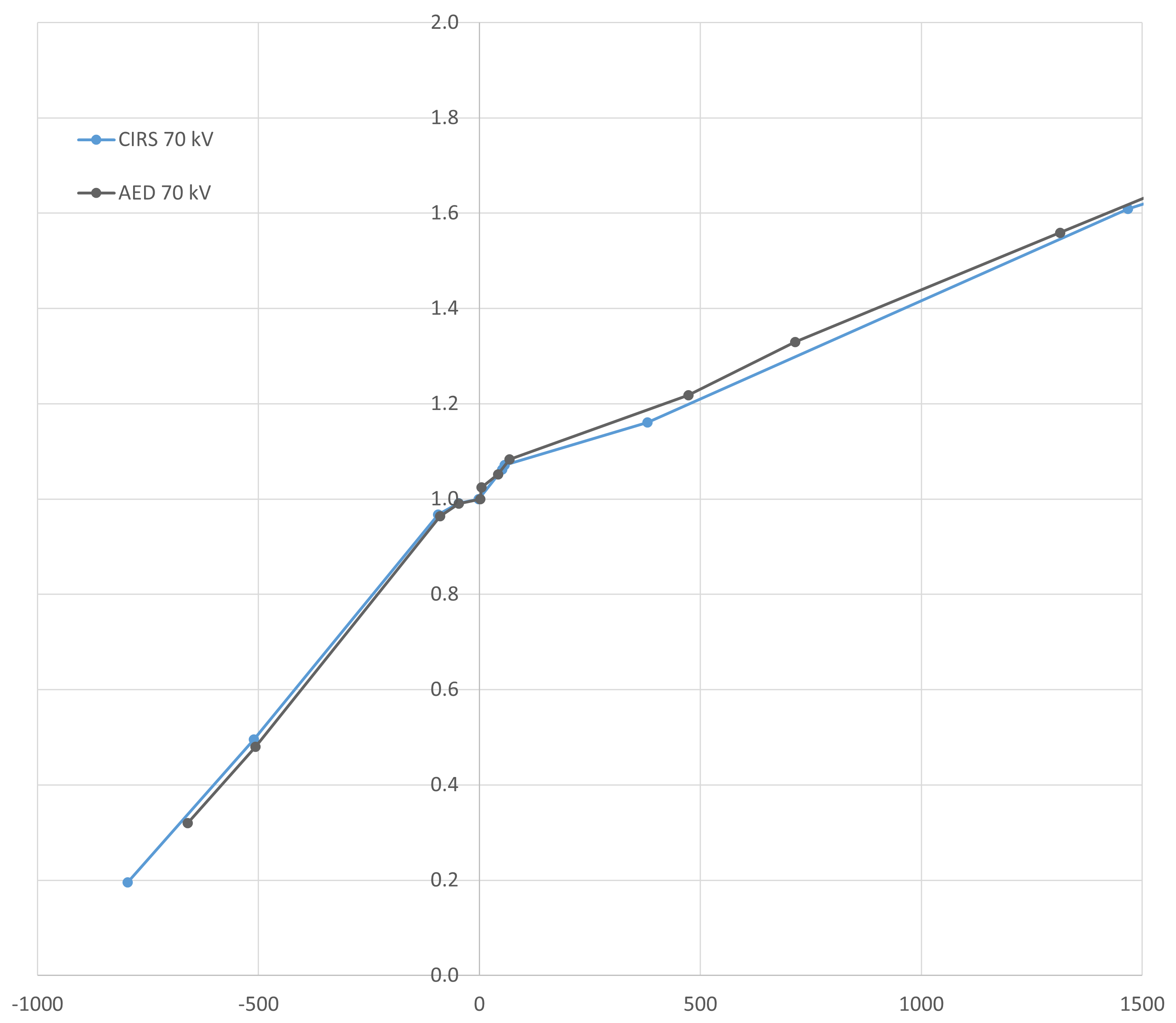
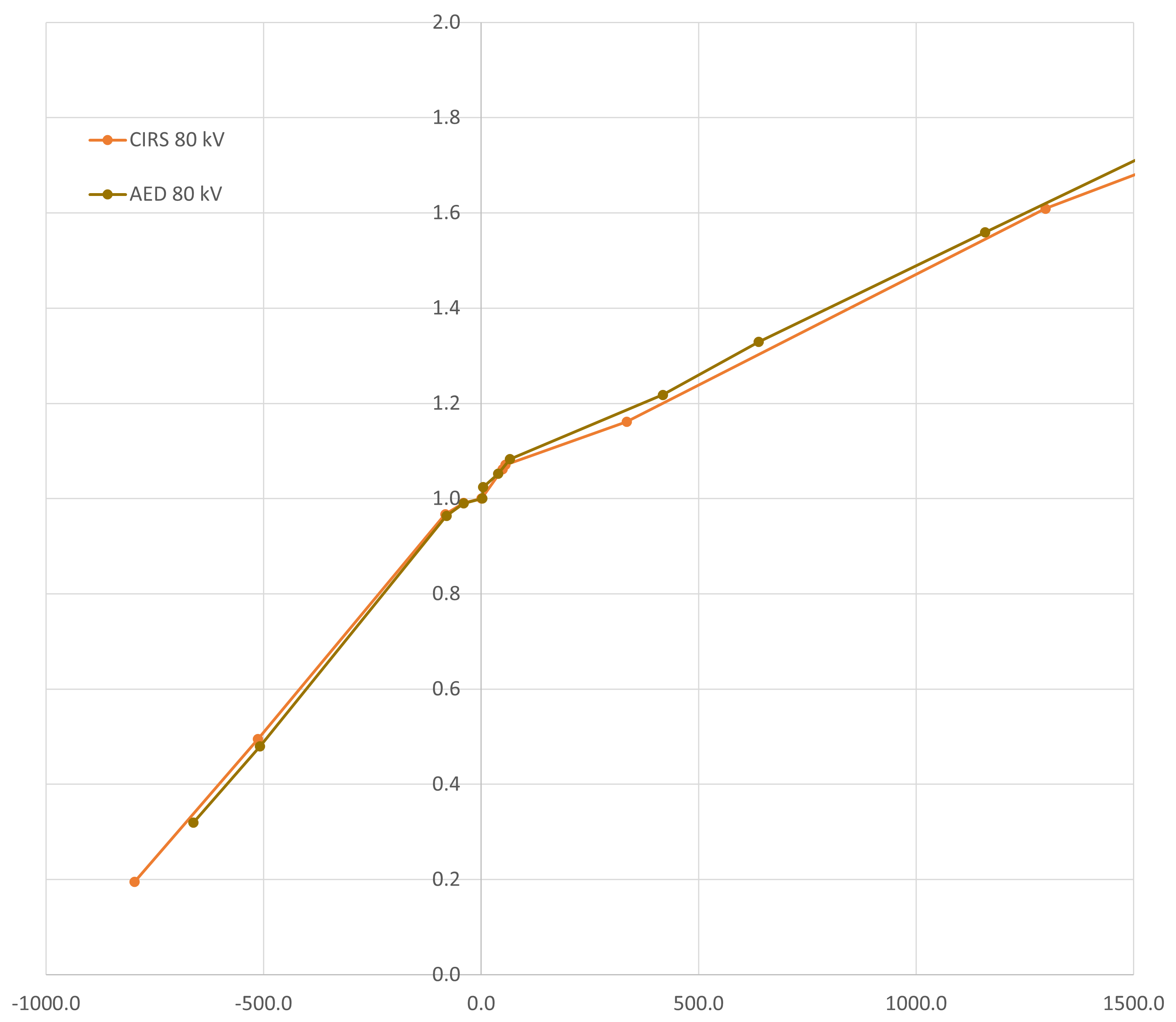
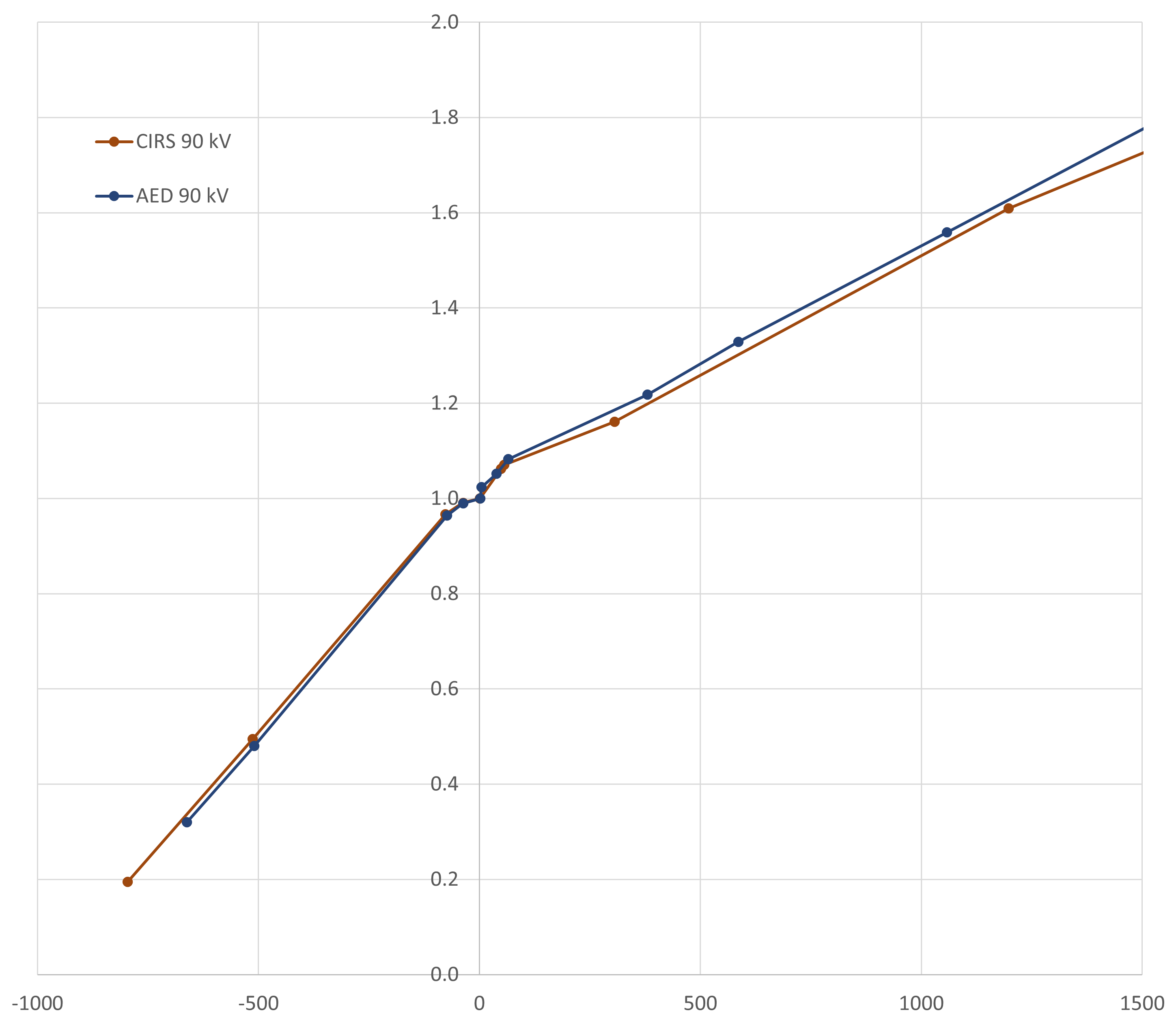
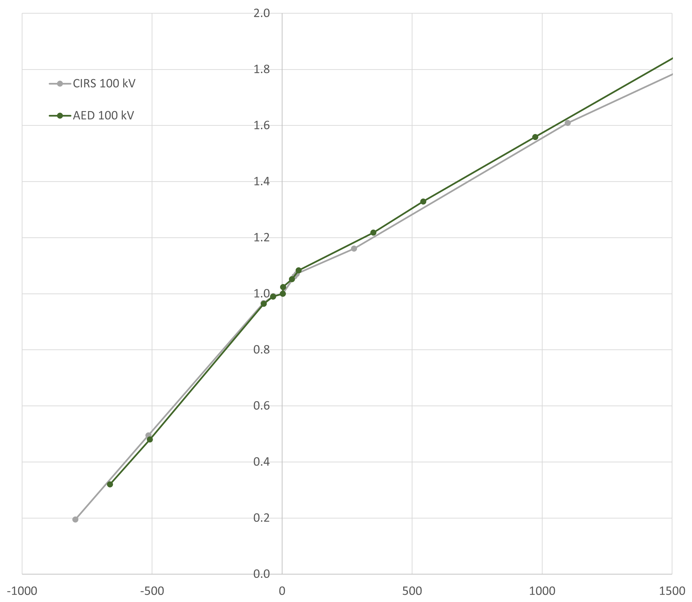
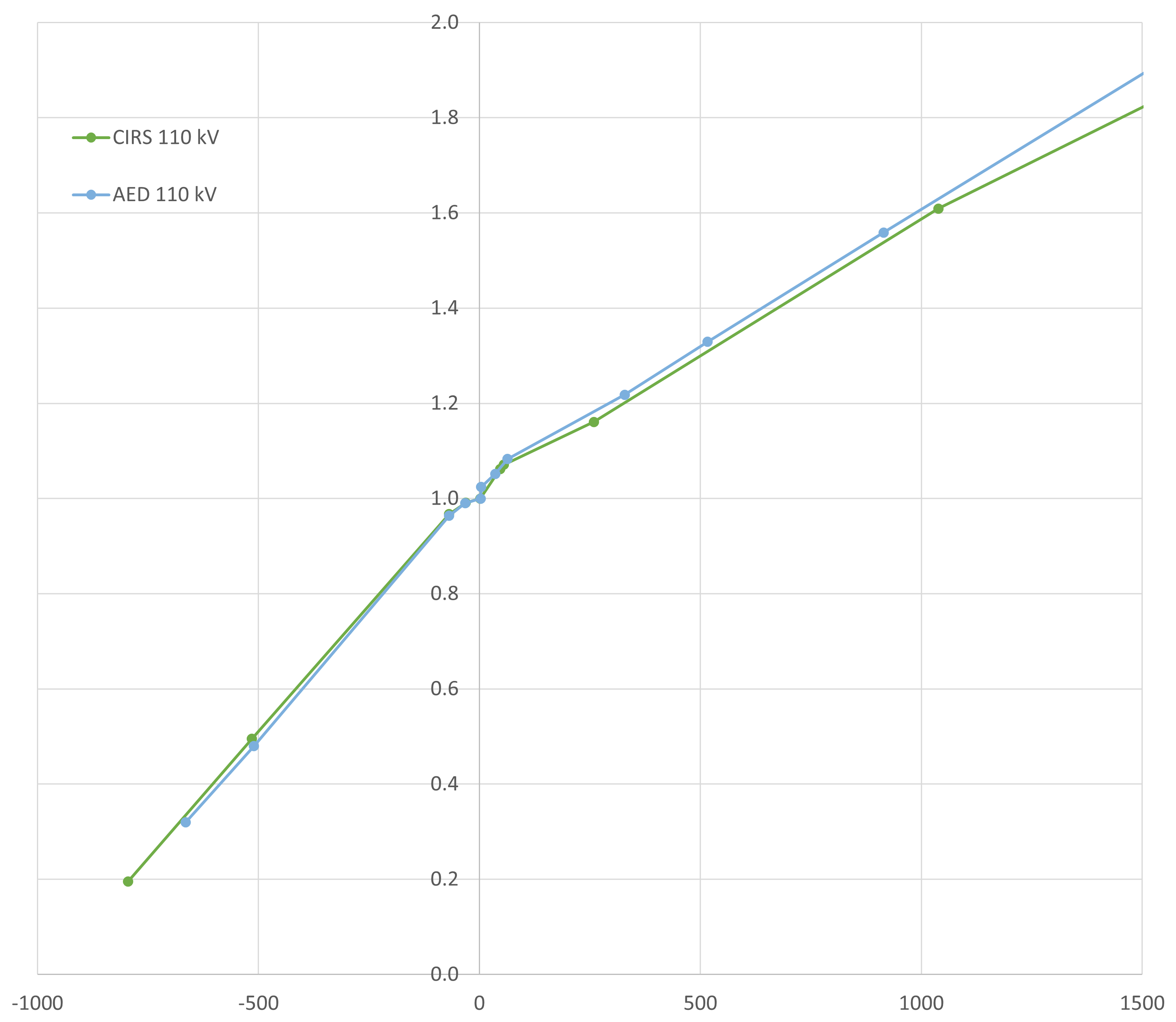
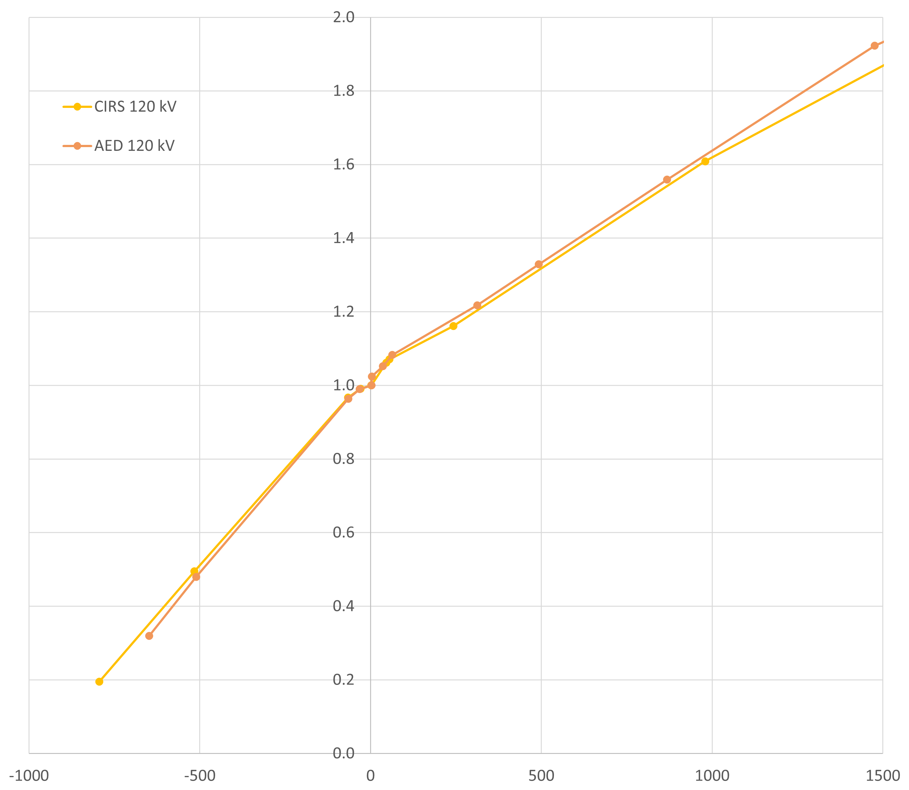
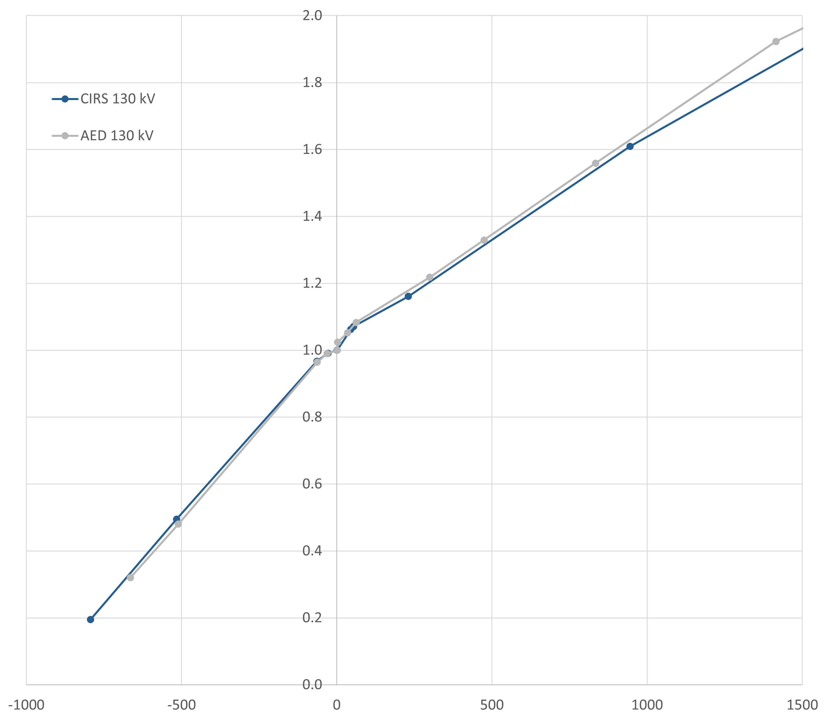
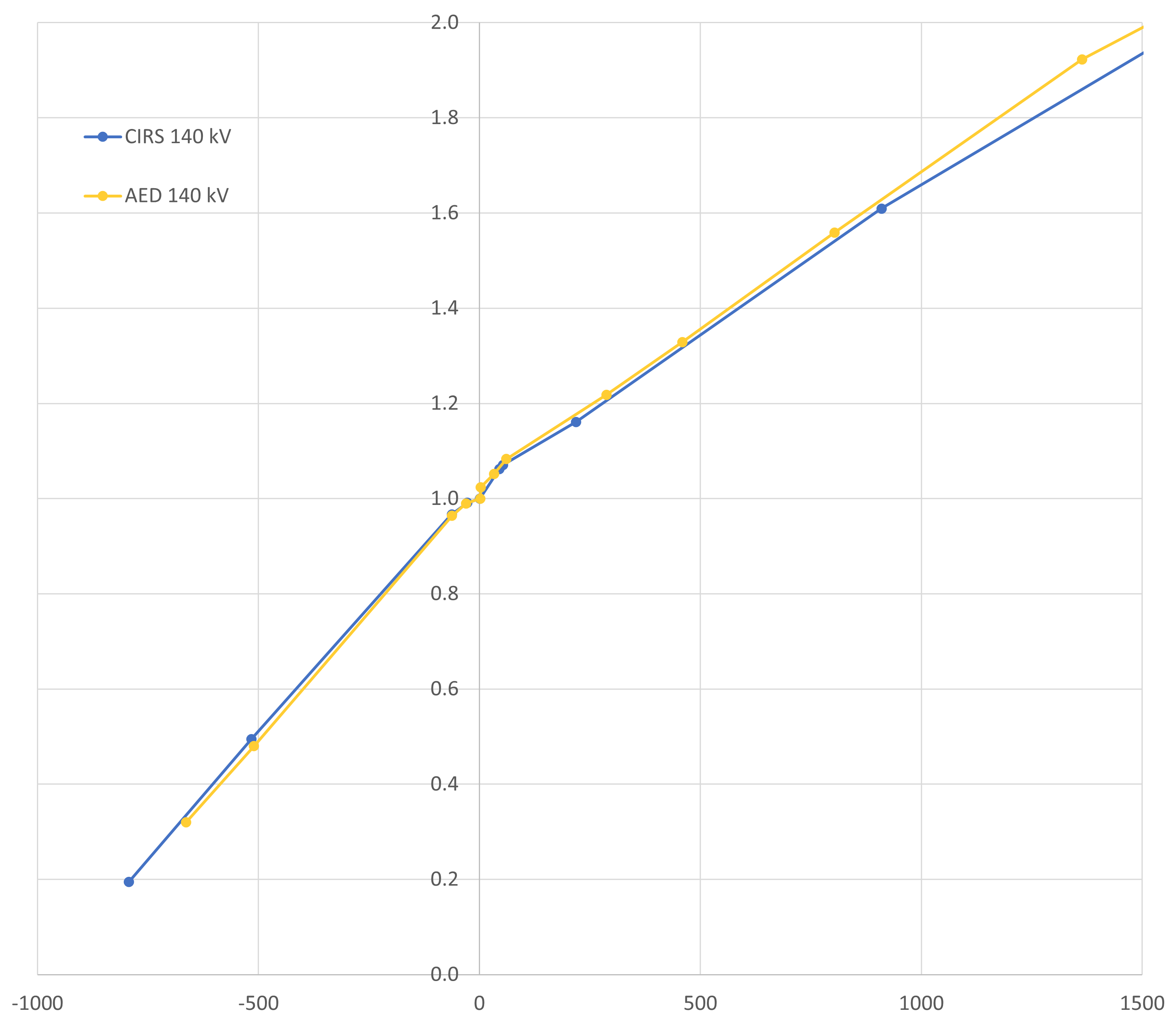
The horizontal (HU) axis covers the most relevant range up to 1500 HU.
Titanium Differences
Differences for titanium are somewhat larger (especially at low kV settings):
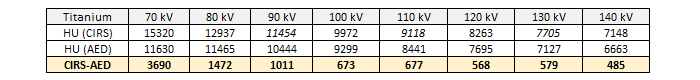
There are a few ideas, but none provides a satisfactory explanation. The AED statistics is much better (larger rod diameter3, many slices evaluated, round ROI), but even the lowest HU point value inside the CIRS rod is higher than the ROI-averaged AED value.
Machine: TrueBeam
Linacs with attached X-ray tubes do not appear to be the target audience of RapidCHECK, as it is not possible to select the manufacturer "Varian" in the software (same with Elekta), which is why the machine has to be defined as4 "Other CT".
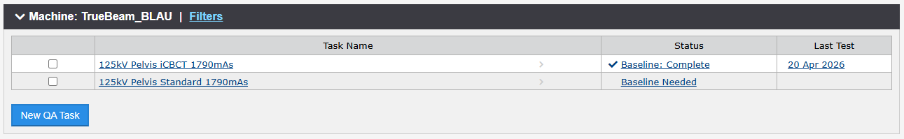
On the TrueBeam, the CBCT Reconstructor offers two types of image reconstruction: the older one called "Standard", and the newer, GPU-based "iCBCT". We set up QA Tasks for both types.
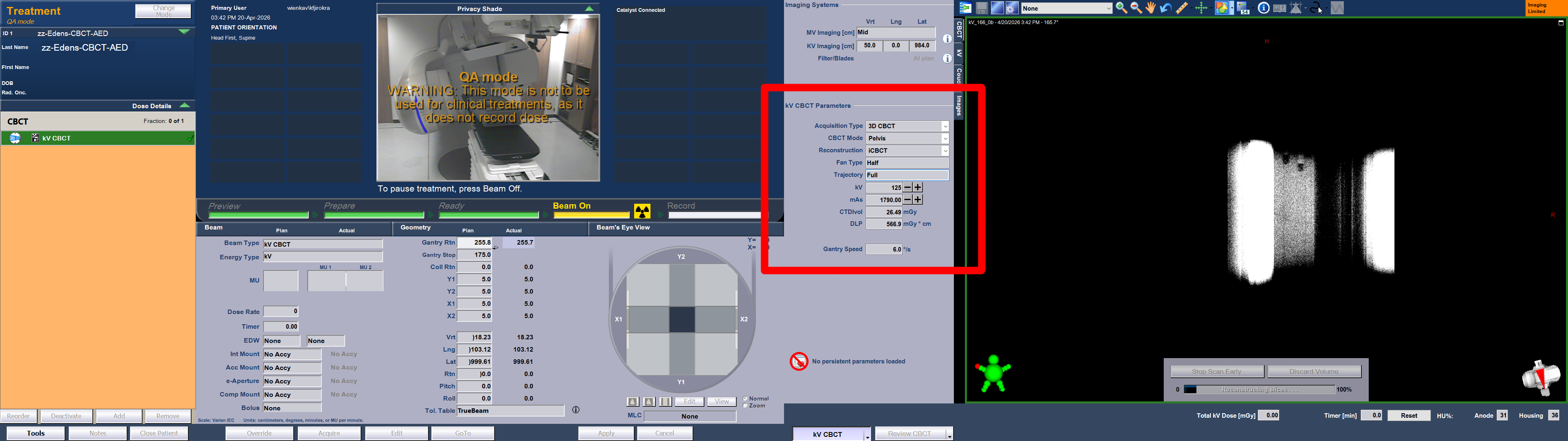
Since the occasional dose calculation on CBCT images is mainly carried out in the pelvic region, we limit ourselves to 125 kV and the "Pelvic" scan in RapidCHECK.
Here, we describe the generation of a baseline for iCBCT on TrueBeam_BLAU in a little more detail.
The process starts with the acquisition of the CBCT images on the TrueBeam. The AED on the treatment couch is set to the "low" configuration described above. The relevant kV settings are shown in the red box (the mAs value was increased here compared to patient scans to reduce noise):
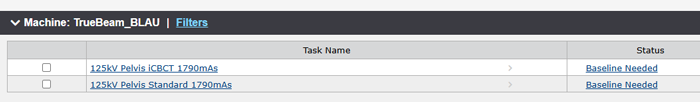
In RapidCHECK, we set up the QA Tasks and click on "Baseline Needed" to upload the iCBCT images:
The analysis starts immediately. For 87 slices, it takes about 30 seconds until the results appear:
Note that in contrast to the images of the goOpenPro, all rods were immediately identified by RapidCHECK. This supports our theory regarding the ring artefacts in the first few slices on the goOpenPro images.
We want to go through most of the sections of the page (did we already mention that RapidCHECK is browser based?).
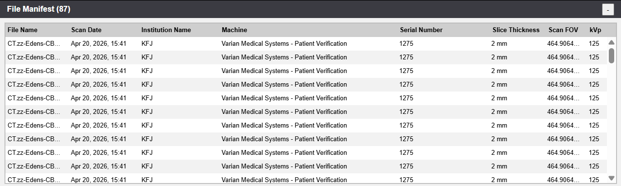
The so-called File Manifest lists the uploaded files:
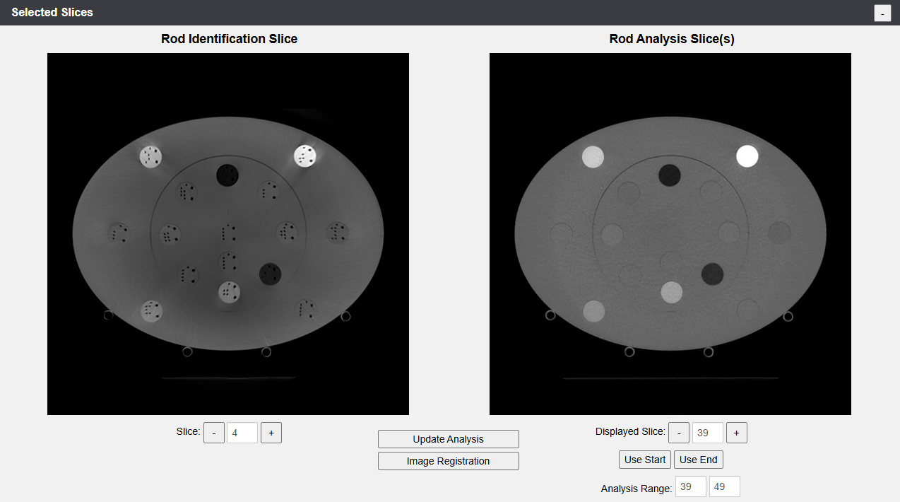
The Selected Slices provide a larger view of the Rod Identification Slice and the Start/Stop Slices, with the option to change them:
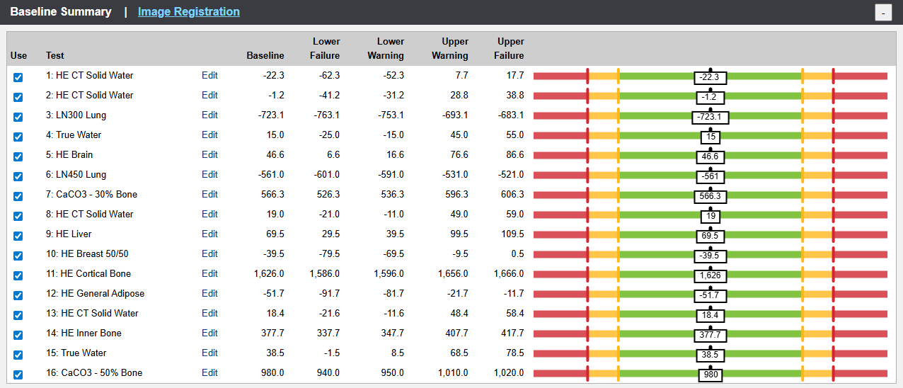
The Baseline Summary displays the suggested values regarding the Warning and Failure levels for each material:
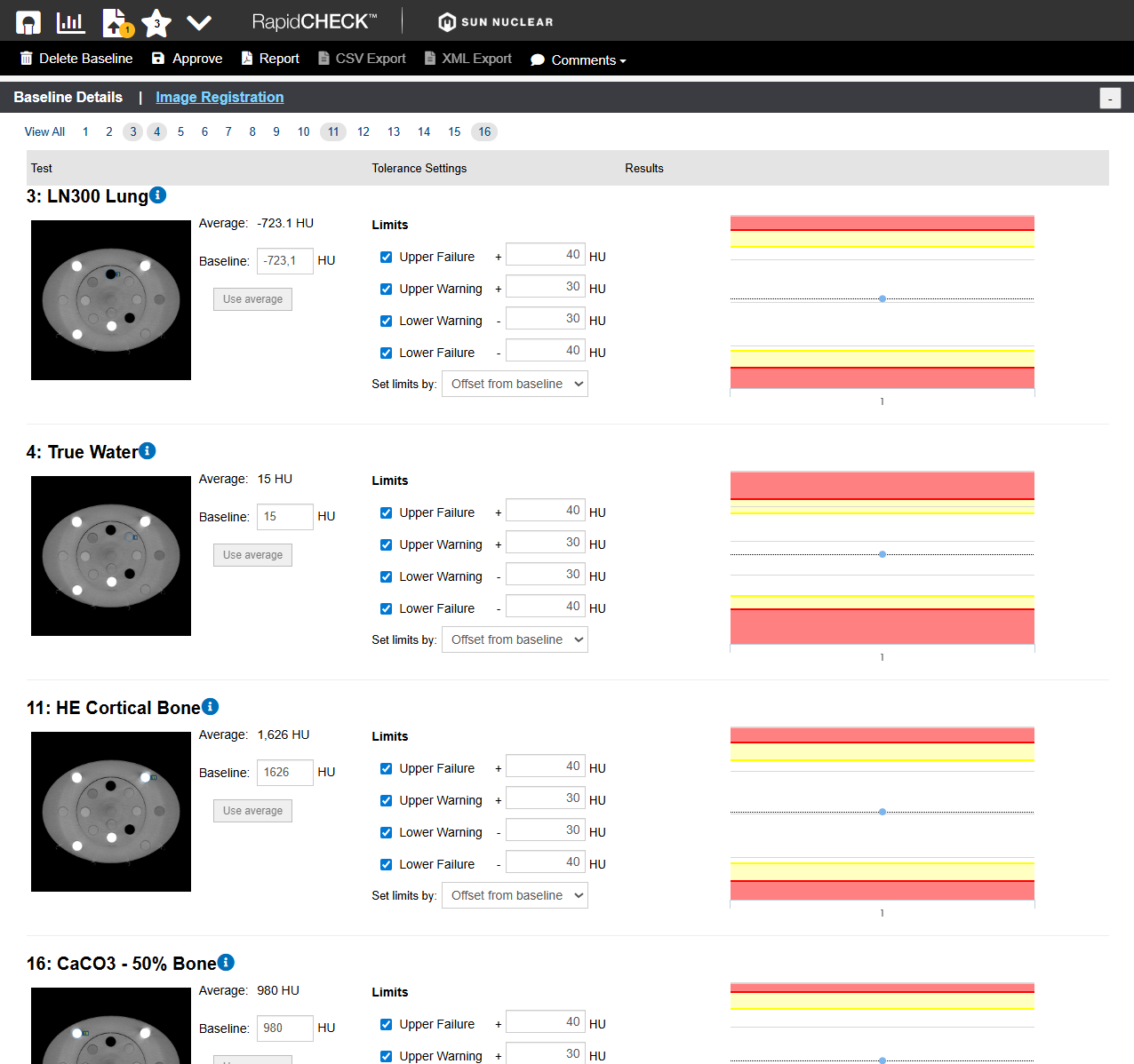
Via the "Edit" link in each line, all values can be changed. This can also be done in the Baseline Details, where we display the most important materials: LN300 Lung, True Water, Cortical Bone and CaCO3-50% Bone:
We will leave all values as suggested by RapidCHECK.
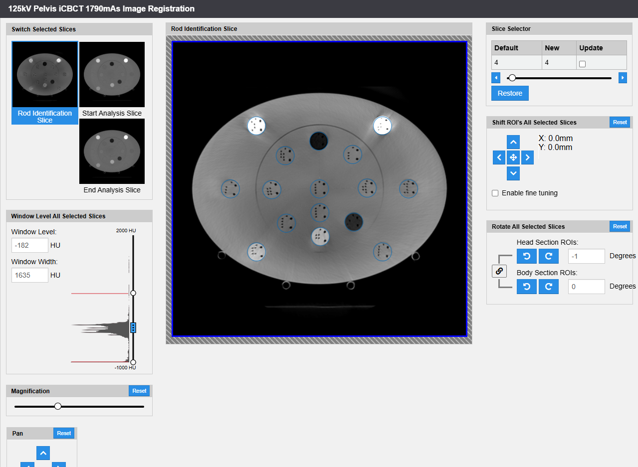
Because it is a baseline, Image Registration should be checked as well. Note that RapidCHECK detected (and corrected) a 1 degree rotation of the inner (Head) section of the AED phantom:
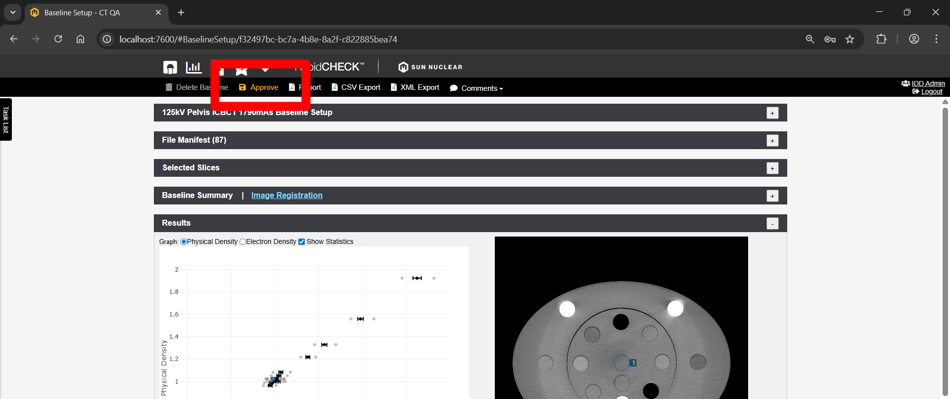
Once we are happy with the analysis, which should serve as a baseline for this QA Task, we click on the "Approve" button in the menu:
This completes the baseline setup for the iCBCT task on TrueBeam BLAU.
Conclusion
RapidCHECK seems to be a valuable tool for the fast analysis of AED scans. We therefore plan to implement a scheme of constancy checks for the goOpenPro and the TrueBeams, and currently discuss the frequency of checks. Especially if several kV settings and scan protocols are in clinical use, the time saving potential is significant.
Notes
1 Since we stopped using AAA some time ago, we are mainly interested in Mass Density.
2 We usually construct our calibration curves with measured points up to the density of titanium, and add a "synthetic" (not measured) "Gold" point at 32767 HU (the highest possible value which can be entered in Eclipse at the present time) to avoid warnings in Eclipse during dose calculation.
3 The diameter of the AED titanium rod is 12.7 mm, in the CIRS it is 10 mm.
4 Alternatively, one can choose the manufacturer "Siemens", which is not wrong in our case.