The Road to ART - Dose Planning on CBCT Images
The ability to calculate meaningful dose on Cone Beam CT (CBCT) images of a Linac is one of the prerequisites of Adaptive Radiotherapy (ART). We do not want to go into the details of ART here, because our current TrueBeams are not and will not be1 equipped with the latest innovations such as HyperSight, and true support for ART workflows is only available on the Ethos platform.
However, we can walk a few steps on the "Road to ART". Interestingly, as we will see, it is not unthinkable to perform even the premier class of ART, Online ART, on our 13 year old systems.
In the literature2 one finds systems where the dose calculation step of ART is performed, after overriding bulk-density, on water and bone alone.
If we look at typical TrueBeam CBCT images (right), we have to say that bulk-density overrides do not necessarily come to our mind:
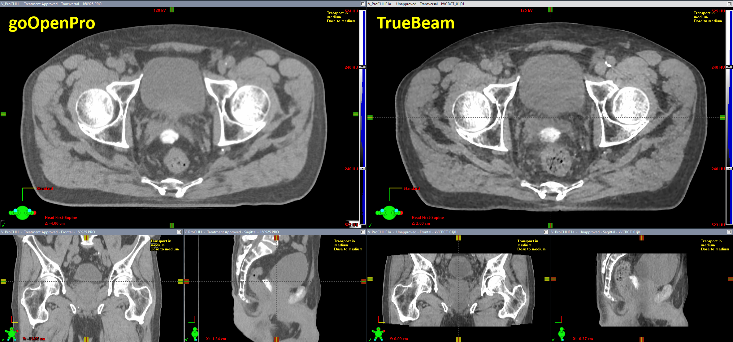
(Image quality of goOpenPro (left) and TrueBeam (right). Window/levelling is identical.)
The GPU-based iterative CBCT reconstructor (iCBCT), which we implemented in 2021, produces excellent images with very good low contrast resolution. The TrueBeam image looks sharper than the image of the goOpenPro, but this is mainly because the CBCT image has a resolution of 0.9 x 0.9 mm (matrix size: 630 (after couch enlargement) x 512 px), whereas the resolution of the goOpenPro image shown is 1.2 x 1.2 mm (512 x 512 px).
The quickest way to find out which is which is scan length. The CBCT image shown is about 16 cm long. However, this can be misleading if Extended Scan (multiple consecutive acquisitions are combined in one reconstruction) is used.
Preparing the New Scanners
In the same way as a spiral CT is prepared for treatment planning, a CBCT first has to be introduced in the dose planning chain as an imaging device. In the Varian world, this is easy. During TrueBeam installation, the two X-Ray tubes with their CBCT functionality were created in the ARIA database and show up in RT Administration under Radiation and Imaging Devices (yellow):
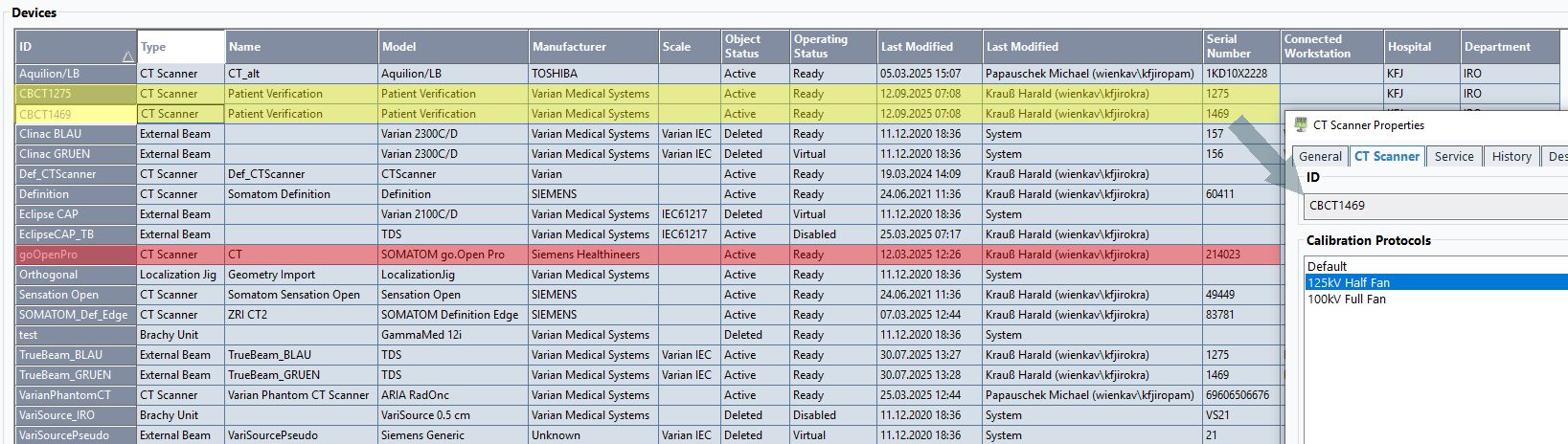
(Radiation and Imaging Devices in RT Administration. TrueBeam CBCTs in yellow, goOpen Pro in red.)
If the imaging device is a CT, it has a "CT Scanner" tab where the various calibrations are listed (on the goOpenPro, the list is quite long). Calibration curves can be visualized here, but editing is only possible in Beam Configuration workspace.
The ID (first column) and the serial number of the scanner (column 11) are typically the minimum information necessary to match a certain CBCT scan to a certain calibration curve, e.g. for mass density. More match rules (kV, reconstruction kernel etc.) are optional. This applies to both the TPS and secondary dose calculation systems such as VERIQA.
CBCT Terminology
On the TrueBeam, when a 3D CBCT acquisition is set up at the beginning of the first treatment session, the therapist selects3 a certain CBCT Mode (e.g., Pelvis, Spotlight, Head_HQ etc.) which matches the anatomy and purpose. This auto-fills4 the following parameters:
- The Reconstruction is either iCBCT or the older Standard reconstruction. Additional recontruction modes can be defined by the user to include, for instance, a specification of slice thickness. While the standard slice thickness is 2 mm, we defined an additional iCBCT-1mm reconstruction, which is used for stereotactic treatments.
- If the Fan Type is Full, this means that the imager is centered laterally. Half means it is shifted laterally to cover the full body outline, which is important for dose calculation.
- Trajectory is typically Full or Half, and specifies the angle of Gantry rotation during acquisition.
- A kV setting is also auto-filled, but can be adapted if necessary. Currently, all our CBCT mode templates use one of the following kV settings: 100 kV (for Head and Head_HQ), 125 kV (Pelvis, Spotlight, Thorax) or 140 kV (Pelvis Large).
There is no need to create a density calibration protocol for each CBCT Mode separately, because we can group them. Nearly all our CBCT Modes can be divided into two groups5:
- 125 kV Half Fan
- 100 kV Full Fan
This is possible because nearly all 100 kV CBCT Modes use a centered detector ("Full Fan") whereas all 125 kV CBCT Modes are Half Fan modes. The only exception from this rule is Spotlight, which is a Full Fan scan with 125 kV. However, Spotlight is not useful in the context of ART, because it cuts out a section of the body.
For our steps on the road to ART, we want to focus on the Pelvis CBCT mode and the iCBCT reconstructor.
HU Calibration of CBCT Modes
In order to be able to calculate dose om CBCT images, we first have to measure EDens and MDens calibration curves.
Acquiring these curves is straightforward, just like on the goOpen Pro. This time, we used the Advanced Electron Density (AED) phantom. The evaluation had to be done in manual mode because Pythia is still working on a solution to our problem.
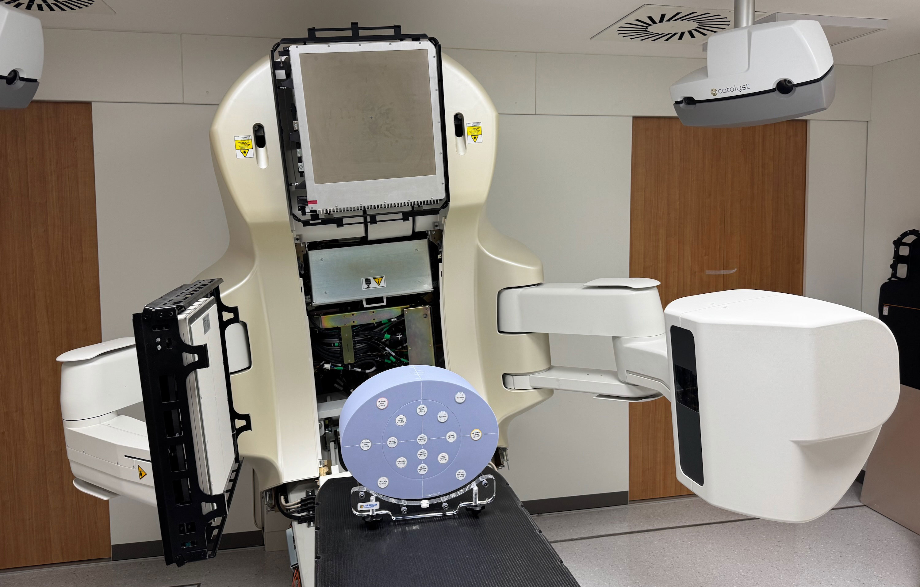
(AED phantom on the TrueBeam. Some covers are off, because this happened during a PMI session.)
The density of the AED's inserts ranged from Lung 300 (0.32 g/cm3) to Cortical Bone (1.923 g/cm3). The CBCT of the phantom (which also shows some artefacts) was evaluated in Eclipse. A ROI size of 18 x 18 px was used:
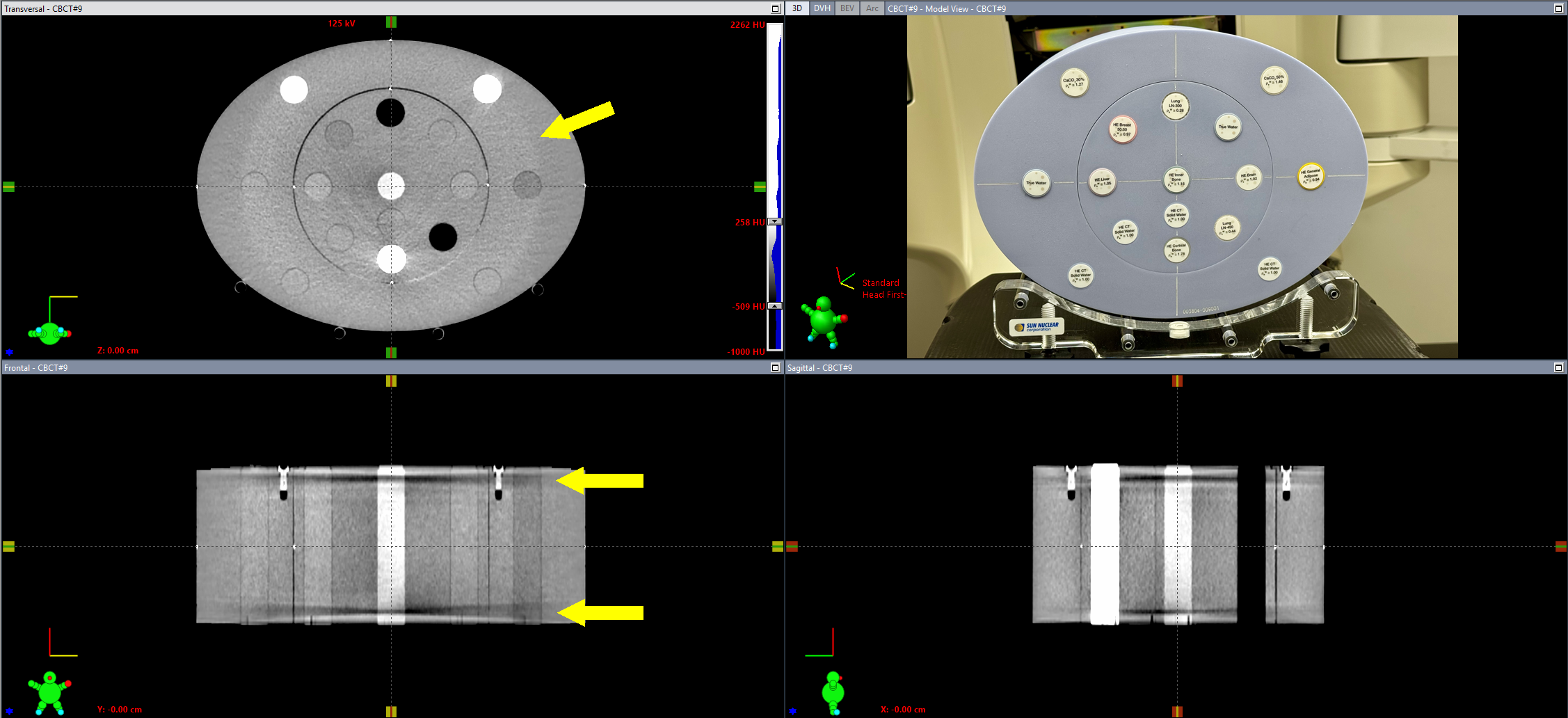
(CBCT image of the AED phantom. Some artefacts are visible.)
From a selection of the datapoints, we constructed EDens and MDens calibration curves for the 125kV Half Fan Calibration Protocol, and applied them to both machines. The same curves were also configured in VERIQA. Now CBCT dose plans can also be sent to VERIQA for a secondary 3D-Monte-Carlo dose calculation (as it is done during Online ART).
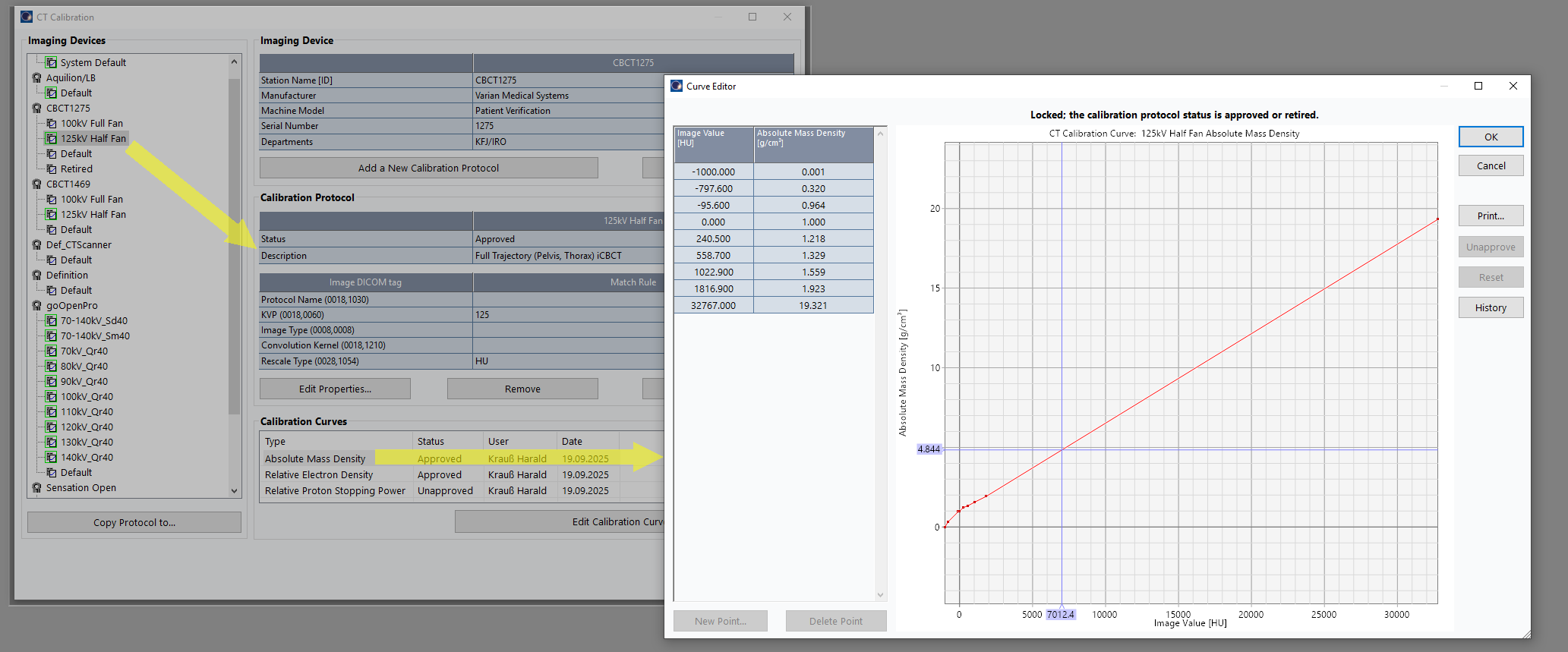
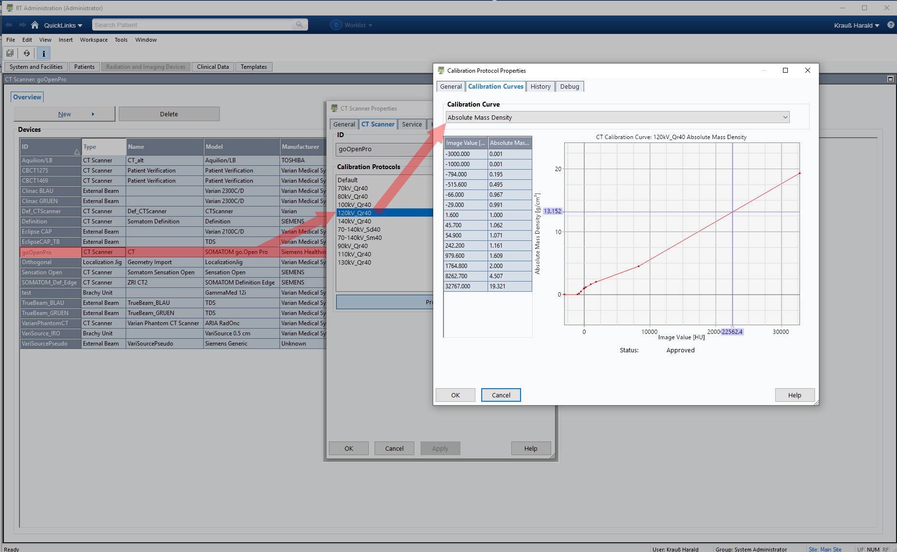
Although TrueBeam CBCT images have a maximum of 7000 HU, we added an additional, virtual "Gold" point (the same as on the goOpen Pro) to prevent warnings during AXB dose calculation. Such warnings would pop up if the calibration curves ends at the "Cortical Bone" point, but material of higher density (like Titanium alloy) appears in the image.
The cursor in the curve points to 7012 HU, which translates to a mass density of 4.844 g/cm3 in the plot. If CBCT dose calculation uses the AXB algorithm, all high density voxels need material assignment. Each material has a valid density range according to the AcurosXB-13.5 Physical Materials Table (Ti6Al4V_ELC: minimum 3.56 g/cm3, maximum 6.21 g/cm3). A measured density of 4.844 g/cm3 would allow the assignment of the Titanium alloy, so all is well.
Recalculating Dose After Session 1
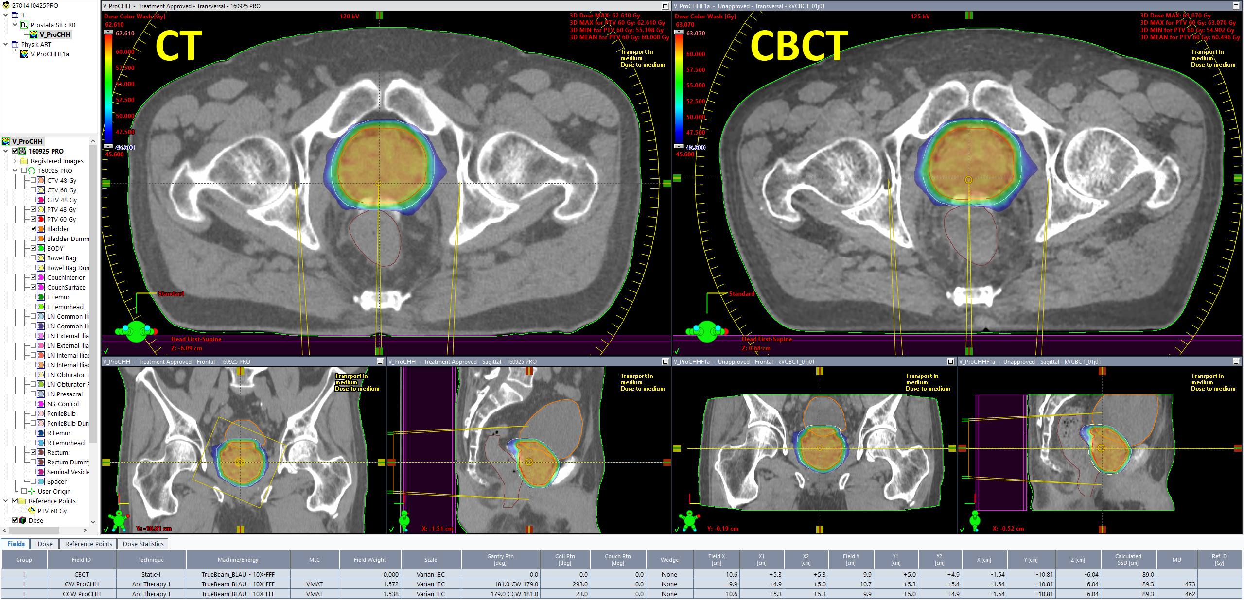
The patient anatomy shown in the first image belongs to a prostate plan with the CHHiP prescription 20 x 3 Gy = 60 Gy to the (central) high dose region, 48 Gy to the periphery. The hydrogel which was used to push the rectum away from the high dose region is also visible.
During the first session, we asked the therapists to aquire a Pelvis scan instead of the Spotlight they would normally choose. During CBCT aquisition, the PerfectPitch couch is always levelled (Pitch = Roll = 0.0°). Then an online match against the planning CT is performed, followed by a 6 DoF couch shift, followed by the treatment.
The elegance of the integrated Varian system is that as soon as the treatment session on the TrueBeam is closed, the CBCT image can be opened on any Eclipse workstation on the network (no export). Immediately after the treatment, we performed the following steps in order to get dose calculated on today's CBCT:
- Switch to Contouring. The CBCT image already has a Structure Set.
- Search BODY. This adds the BODY to the Structure Set.
- Assign a Prostate Structure Template for CBCT, which adds more (empty) Structure containers.
- Add Couch Structures (Exact IGRT, thick)
- Manually contour Bladder, Rectum, and the two PTVs
- Switch to External Beam Planning. In the CBCT Structure Set, select the Physical Material Table (the correct Calibration Protocol, 125kV Half Fan, was assigned automatically by ARIA).
- Copy/paste the clinical plan we just treated. In the copy, change normalization method from "Target Mean" to "Plan Normalization Value", to preserve MU.
- In the plan copy, we assign the CBCT Structure Set instead of the planning CT Structure Set.
- This brings up a selection dialog which Registration to use (the CBCT had a second offline registration, which was performed to check the online registration). We choose the Online Registration from the 1st session. Now the isocenter is placed according to this registration, and we can calculate dose.
Dose on the CBCT is calculated with the same parameters as in the treatment approved plan (AXB, 2mm grid). Since the patient had no metal implants, we skipped the "Segment High Density Artifacts" step in Contouring. Consequently, no material assignment was necessary.
It is good to see that target doses (DVH curves in red and yellow) are very close: in today's session (triangles) the mean PTV60 dose was 60.496 Gy (+0.8%), whereas the original plan (squares) had been normalized to target mean (60.000 Gy).
During contouring of the CBCT, we had already seen that the rectum - in spite of the SpaceOAR hydrogel - was a little closer to the high dose region than in the planning CT. This is confirmed by its mean dose, which is a little higher:
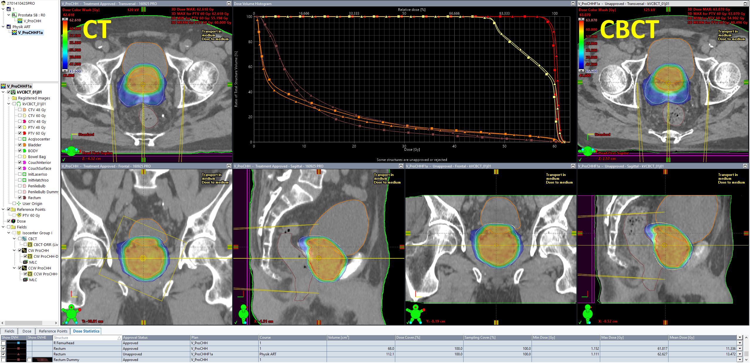
All dose values are for 20 sessions. A mean dose of 13.472 Gy instead of the 11.336 Gy in the original plan means that if the anatomic situation in all 20 sessions would be as it was today, rectum mean dose would be 2.1 Gy higher than planned. We all know that this is unlikely. This is exactly what a good ART management system should provide: keeping track of all the doses for (example) 20 individual plans with 20 individual sets of DVHs.
Summary
In this experiment, we walked a few steps on the road to ART. We did not use a stopwatch but we guess the whole chain, from CBCT aquisition to the calculated plan of the day, took less that 30 minutes.
From here, it would be easy to walk a few steps further down the road, fire up the Photon Optimizer (PO) in Eclipse and reoptimize the CBCT plan based on today's anatomy. Since PO and AXB use the GPU for both optimization and dose calculation, this would probably take another two or three minutes, but without compromises in accuracy, because the same optimization and dose calculation settings can be used as in the original plan. And bulk-density overrides are definitely not required.
Notes
1 For many innovations such as HyperSight, Varian typically draws a line whether a machine is elegible for an upgrade or not, by defining a minimum serial number. In our case, this line is drawn at S/N 2000. Since our TrueBeams are below (1275 and 1469), an upgrade is not possible.
2 Maureen L. Groot Koerkamp et al., Bringing online adaptive radiotherapy to a standard C-arm linac, Physics and Imaging in Radiation Oncology, Volume 31, 100597, July 2024, https://doi.org/10.1016/j.phro.2024.100597
3 The settings are saved for the next treatment, but can be changed in a later session.
4 In the sense of a default setting. If there are alternatives in the CBCT mode template, e.g. the default reconstruction in the template is iCBCT but the user for some reason wishes to use Standard, this setting can be changed.
5 We ignore the 140kV Pelvis Large, because it was never used clinically.