The doughnut is a manually constructed dynamic leaf sequence, which consists of 20 single shapes:
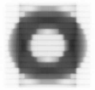
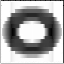
Only five shapes are really necessary, the others can be generated by mirroring. The idea was to have a very general movement (where leaves move in both directions) and a lot of closed leaf pairs. When the planned gaps are zero, the shaper application (from which the above screenshots are taken) would simulate a film that has an ideal fluence distribution (without gap transmission):

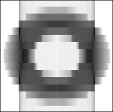
One must not expect this distribution on film, because fluence is also transmitted through the gaps (and between the leaves). On the other hand, when treating this ideal pattern with zero gaps, a lot of hold-offs will occur, because closed and moving leaf pairs are treated differently by the MLC control mechanism than leaf pairs that have a small gap. Here is the result on film with zero leaf gaps:
The parameter LeafGapErr of the static MLC calibration defines the physical gap width when all leaves are positioned at zero (along the midline). It can be measured with a feeler gauge. Usually, the leaf gap is set to 0.2-0.3mm. Simulating this MLC calibration in LFC is easy. One must simply add a certain offset to all leaf positions at all times when calculating the true fluence.
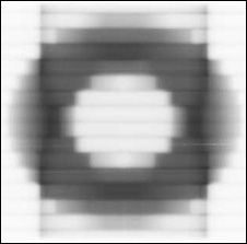
If a constant gap of, say, 0.2mm is added to the above sequence, also the shaper would simulate this:

Treating this file is possible without hold-offs in a few seconds. The scanned film,
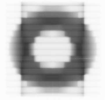
does not look that different, which means that the 0.2mm extra gap does not play a big role. Here is the true fluence calculated with the LFC and a planned gap of 0.2mm (the corresponding dynalog calculation):
Error fluence is still underestimated. Two questions arise:
The second question is certainly more interesting than the first. On film, the gap transmission will be governed by the dosimetric leaf separation (DLS) that includes also the effect of the rounded leaf edges (the DLS is also an important parameter in the Helios configuration). So the DLS is a good value to start with. If 2mm (at isocenter) are added in the LFC calculation (1mm for each leaf bank), one gets the following true fluence distribution from the dynalog files (left image).
 |
 |
Looks already quite similar to the film scan (right image), if one ignores the interleaf leakage! Differences arise, among others, from the preliminary lookup tables of the film scan.
Application: the dynalog file analysis, once proven to be to be equivalent to radiographic film and further refined, will speed up pretreatment verification. Only point dose measurements will be necessary in order to verify monitor units. Relative fluence distributions will be verified with the dynalogs.
Evaluating the dynalogs record by record, the treatment can be animated (download AVI):
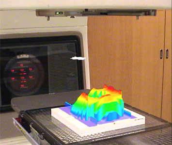
Plotting this in 3D is also possible. In this movie, the true fluence calculated from dynalog with 2mm extra gap at isocenter is projected on the Clinac tabletop. The leaf opening is cycling above the fluence like a magic carpet (download AVI, DivX codec required).