MLC Dosimetry
1.) Penumbra: Comparison
between MLC and Jaws
I have compared the field
penumbra of MLC fields to the penumbra of conventional fields of the same size.
Setup:
- All measurements were
done with a PTW MP3 waterphantom.
- SSD was 90 cm, Gantry
0 deg, Collimator 0 deg.
- A PTW 31002 thimble chamber
(0.125 cm3) was positioned with its center at Isocenter, at a water depth
of 10 cm.
- The chamber was mounted
crossplane. Due to the almost square chamber volume (5.5 mm diameter, length
6.5 mm), the chamber stem effect was neglected.
- Scans were made inplane
and crossplane, scan resolution was 1 mm, measuring time 0.5 s per point.
- The Clinac was set up
to beam on at a doserate of 500 with dose servo off.
- Measurements were done
for the two photon energies 6MV and 15MV.
- Jaws were set at the
nominal field sizes of 4*4, 10*10 and 20*20 cm for "Jaw-fields".
- For "MLC-fields"
the jaws were set at the recommended settings of 4.4*5.6, 10.4*11.6 and 20.4*21.6.
The larger value is always crossplane, the direction of leaf movement.
- Closed leaves of MLC-fields
were closed off-axis, otherwise the inplane scans would run through the leaf
abuttment region.
- Penumbra was defined
by 80% - 20%.
- All values in the tables
are given in mm.
- PTW Coordinate system: when
seen in BEV, Gantry on top, +x points to the Gantry (inplane), +y to the right
(crossplane). See Figure 1 for orientation of the waterphantom.
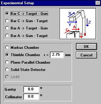 |
Figure 1: Coordinate Systems
(PTW Mephysto measuring Software)
- Penumbra
|
- caused by
|
- -x
|
- X1-jaw, MLC
Carriage B
|
- +x
|
- X2-jaw, MLC
Carriage A
|
- -y
|
- Y1-jaw
|
- +y
|
- Y2-jaw
|
Coordinate System Mapping
Results:
|
X06,
4*4
|
Jaws
|
MLC
|
MLC-Jaws
|
|
-x
|
5.56
|
5.39
|
-0.17
|
|
+x
|
5.53
|
5.35
|
-0.18
|
|
-y
|
5.89
|
6.46
|
+0.57
|
|
+y
|
5.91
|
6.52
|
+0.61
|
|
|
X06,
10*10
|
Jaws
|
MLC
|
MLC-Jaws
|
|
-x
|
6.64
|
6.34
|
-0.30
|
|
+x
|
6.63
|
6.30
|
-0.33
|
|
-y
|
6.98
|
7.53
|
+0.55
|
|
+y
|
6.98
|
7.65
|
+0.67
|
|
|
X06,
20*20
|
Jaws
|
MLC
|
MLC-Jaws
|
|
-x
|
7.84
|
7.40
|
-0.44
|
|
+x
|
7.71
|
7.31
|
-0.40
|
|
-y
|
7.96
|
8.91
|
+0.95
|
|
+y
|
7.98
|
8.97
|
+0.99
|
|
|
X15,
4*4
|
Jaws
|
MLC
|
MLC-Jaws
|
|
-x
|
6.36
|
6.31
|
-0.05
|
|
+x
|
6.30
|
6.23
|
-0.07
|
|
-y
|
6.66
|
7.36
|
+0.70
|
|
+y
|
6.69
|
7.43
|
+0.74
|
|
|
X15,
10*10
|
Jaws
|
MLC
|
MLC-Jaws
|
|
-x
|
7.09
|
6.93
|
-0.16
|
|
+x
|
7.03
|
6.89
|
-0.14
|
|
-y
|
7.36
|
8.01
|
+0.65
|
|
+y
|
7.35
|
8.09
|
+0.74
|
|
|
X15,
20*20
|
Jaws
|
MLC
|
MLC-Jaws
|
|
-x
|
7.72
|
7.53
|
-0.19
|
|
+x
|
7.70
|
7.49
|
-0.21
|
|
-y
|
7.97
|
8.86
|
+0.89
|
|
+y
|
8.00
|
8.83
|
+0.83
|
|
Penumbra size (in mm), Difference
MLC-penumbra minus Jaw-penumbra (in mm)
Discussion:
When the curved face of
the leaves defines the field edge, the penumbra should be somewhat larger than
with jaws. This can be seen in the tables, where the difference MLC-penumbra
minus Jaw penumbra is larger for +y/-y edges. The increase in penumbra lies
between 0.55 and 0.99 mm. The inplane penumbra for MLC-fields is always slightly
smaller than for Jaw-fields.
2.) Leaf Transmission
For determination of the
pure interleaf-transmission (between adjacent leaves) the leaves should not
be shielded by the carriage guideplate (which gives some additional shielding,
see below). Two MLC shapes define the setup for this test, one shape for each
carriage.
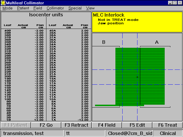 |
Figure 2: Test pattern for carriage
B transmission test
Setup for Carriage B
Transmission Test:
- The jaws are set to X1
= 10 cm, X2 = 0 cm, Y1 = Y2 = 5 cm (dashed lines in Figure
2). This sets up an asymmetric field of 10*10 cm. The scanline for the waterphantom
will be 5 cm off axis, through the center of the field defined by the jaws.
- The other parameters
are the same as for the penumbra tests above (SSD, chamber, etc.).
- An inplane scan is made
at a depth of 10 cm (Figure 3)
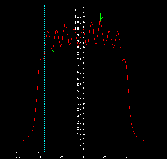 |
Figure 3: Inplane scan with closed
MLC, 15X, Carriage B
- This gives the point
of maximum transmission. The center of the scan shows the gap between leaves
20B and 21B. So the maximum in this scan lies between leaves 22B and 23B.
That is the point where the chamber is positioned for the following dose measurements.
- Dose is measured as an
average over 3 to 5 100MU integrations.
- Then the MLC is retracted,
and again the dose determined. With these two readings, the leaf transmission
can be calculated (see table below).
- Tests were made for both
energies and both carriages (For carriage A, just mirror everything).
Results:
|
Energy
|
Carriage B
|
Carriage A
|
|
X06
|
1.85%
|
1.89%
|
|
X15
|
2.03%
|
2.04%
|
Leaf transmission between leaves
(interleaf transmission)
Discussion:
When leaf 1 is set at the
same value as leaves 2-40 (-2cm), which corresponds more to the true clinical
situation, the closed field is also shielded by the carriage guideplate, and
the X15 transmission is even less (1.77% for X15). The corresponding MLC shape
is shown in Figure 4.
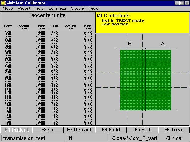 |
Figure 4: Closed MLC where Carriage
guideplate gives some additional shielding (compare leaf 1 here to leaf
1 in Fig. 2)
In the above table, the
difference between the two carriages is not significant. Scans were also performed
at the longest possible field of 40 cm, to "see" all leaves. Scan
resolution was 0.1 mm to 0.4 mm, to catch all details (Figure 5 and 6).
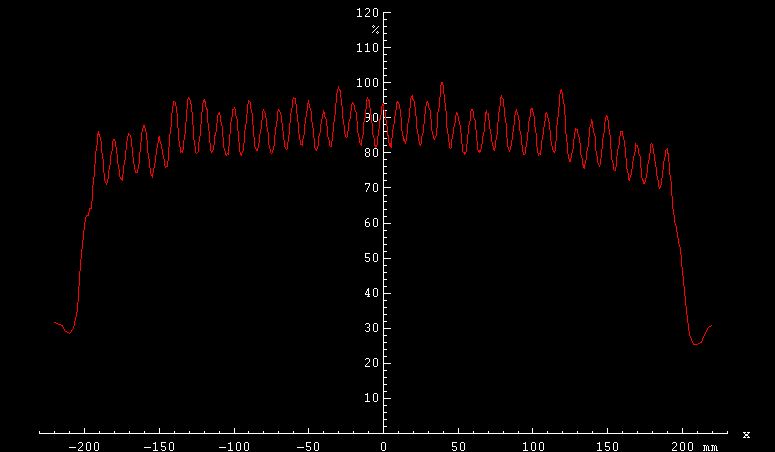 |
Figure 5: Full scan for carriage A, 15X
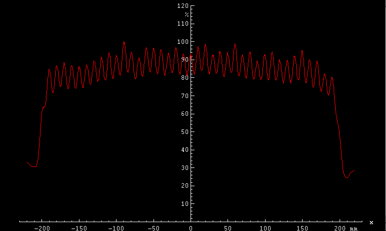 |
Figure 6: Full scan for carriage
B, 15X
back to Medical Physics home
Last modified: Oct 9,
1998 HK


