Standard Applicator Inserts
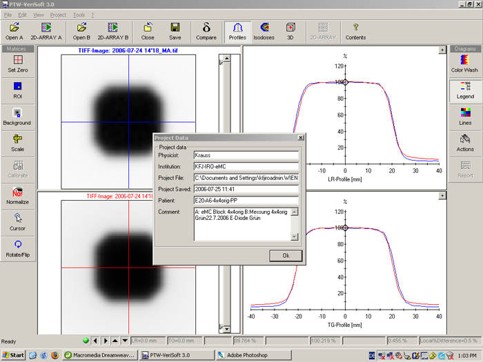
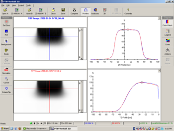
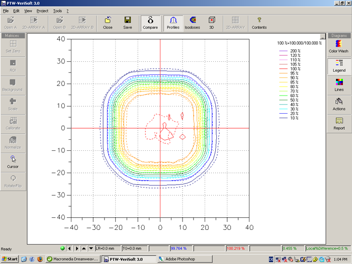
It is interesting to see that for 20MeV, the low dose region outside the field (still under the cerrobend cutout material) is a little underestimated by eMC: the measurement (red) is higher. The reason could be in the measurement (higher sensitivity of the electron diode for low-energy scatter) or the algorithm (IPS model, see eMC1.htm). All our home-made cutouts (see below) are molded a little thicker, so the verification of these could answer the question.
|
Particles |
E06 |
E09 |
E12 |
E16 |
E20 |
4x4orig |
6910000 |
12010000 |
22690000 |
41720000 |
63180000 |
|
6x6orig |
7180000 |
9780000 |
16240000 |
27040000 |
38820000 |
|
10x6orig |
11090000 |
14430000 |
25010000 |
40970000 |
58940000 |
|
10x10orig |
15920000 |
22260000 |
37470000 |
61560000 |
85770000 |
|
15x15orig |
37990000 |
48910000 |
78560000 |
122860000 |
272610000 |
|
20x20orig |
64580000 |
86480000 |
138720000 |
213380000 |
295290000 |
|
25x25orig |
100780000 |
138010000 |
209790000 |
316440000 |
447070000 |
(Values in bold were recalculated with Eclipse 8.1 using the Distributed Calculation Framework with a parallelization factor between 6 and 12).
The calculation times given in the next table are taken from the "Calculation Log". They are realistic in the sense that the calculations were done mid-day, under normal clinical conditions, between all other photon calculations. Since the workload on the calculation servers is not constant, there may be large variations in calculation time, for the same field.
Conditions for calculation were: 3D-image with 300 slices (slice thickness 1mm), grid 2.5mm, 1% accuracy, low 3D-gaussian smoothing.
|
Calc.Time
[s] |
E06 |
E09 |
E12 |
E16 |
E20 |
4x4orig |
87 |
138 |
194 |
274 |
433 |
|
6x6orig |
301 |
436 |
1175 |
1069 |
1827 |
|
10x6orig |
942 |
834 |
3686 |
4901 |
3468 |
|
10x10orig |
1266 |
1048 |
2027 |
5585 |
7140 |
|
15x15orig |
2590 |
3589 |
3882 |
7263 |
1687 |
|
20x20orig |
5917 |
6198 |
24585 |
14661 |
16368 |
|
25x25orig |
4909 |
7844 |
20059 |
17513 |
25739 |
|
Histories/second |
E06 |
E09 |
E12 |
E16 |
E20 |
4x4orig |
79425 |
87029 |
116959 |
152263 |
145912 |
|
6x6orig |
23854 |
22431 |
13821 |
25295 |
21248 |
|
10x6orig |
11773 |
17302 |
6785 |
8360 |
16995 |
|
10x10orig |
12575 |
21240 |
18485 |
11022 |
12013 |
|
15x15orig |
14668 |
13628 |
20237 |
16916 |
161595 |
|
20x20orig |
10914 |
13953 |
5642 |
14554 |
18041 |
|
25x25orig |
20530 |
17594 |
10459 |
18069 |
17369 |
For the home-made inserts, which are usually rectangular or round, having all kinds of field sizes and which are sometimes asymmetric, care has to be taken when planning the field in Eclipse. The actual field sizes in isocenter somtimes differ a little (up to 3mm) from the nominal field sizes. This is due to the molding process. To avoid misinterpretation of the results, it is therefore a good idea first to do the measuement, determine the actual field size, and then calculate the field with the field size determined in the water phantom.
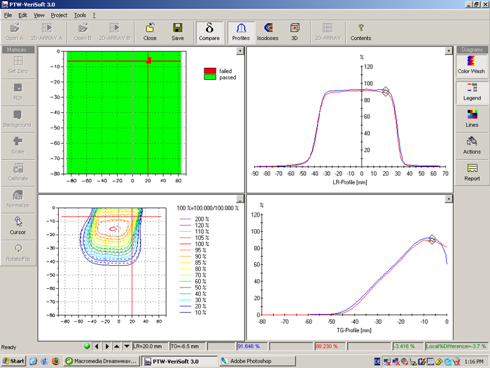
The following images show a typical comparison of a calculated (blue) and a measured (red) crossplane distribution along the depth axis, for a 4x8cm asymmetric applicator insert and 12MeV. The Gantry is at 0°:
