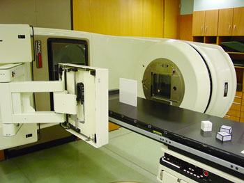
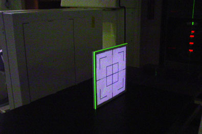
Coincidence of light field and radiation field has to be checked at least quarterly according to the Austrian standard ONORM S5290. After working with radiographic film for eight years, we recently switched to a digital check using the aS500. Another alternative would be the 2D-ARRAY with the MultiCheck software (see elsewhere in this site).
The light field cannot be marked on the detector in the same way as on film (i.e., by punching holes into the envelope). We use a 22x22cm phantom plate with 1mm steel markers, which mark the center plus the field sizes 8x8cm, 16x16cm and 20x20cm. The jaws are set so that the light field matches the 20x20cm field on the phantom (Fig.1 and 2).
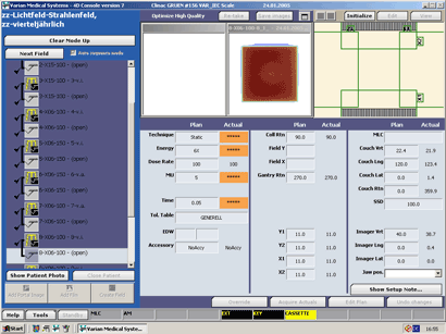
Since the field list is always the same, it is convenient to set up a patient in Varis/Vision for the check. The patient has two Courses, corresponding to the two linacs. Both Courses are active. Identical plans in the Courses contain 10 fields. When performing the check, the fields could be loaded with Auto-Setup. But the Standard requires that the jaws are moved to the target field size one time by opening them starting at a smaller field size, one time by closing them starting from a larger field size. Therefore, jaws are moved manually.
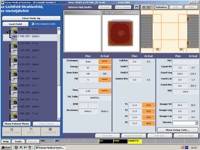
For each target field in the list, an integrated "during" image is acquired with the aS500 detector (appearing colored due to the dose calibration of the integrating mode). Then the jaws open automatically by 1cm and an "after" port image is acquired. The contour representing the 50% field edge of the "during" image is automatically drawn on the "after" port image. This picture is used for evaluation.
 |
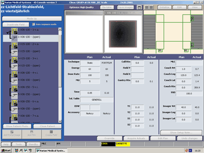 |
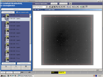
Fig.3: The first image at 6MV, SSD100 is taken (check mark in the field list) and shown in the 4D Integrated Treatment software. |
Fig.4: The "after" port image is taken (double-exposure). |
 |
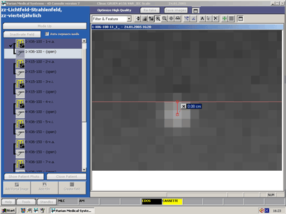 |
Fig.5: Clicking a button magnifies the image. |
Fig.6: All tools that are used clinically to measure and evaluate port images can be used here (e.g., extreme zooming). |
 |
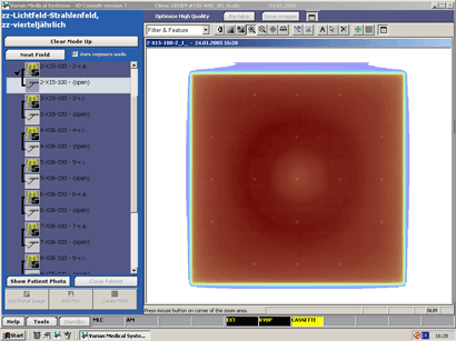 |
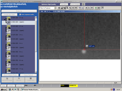
Fig.9: Then the radiation field size is measured in all directions. |
Fig.10: Image contrast is also high enough for 15MV. |
 |
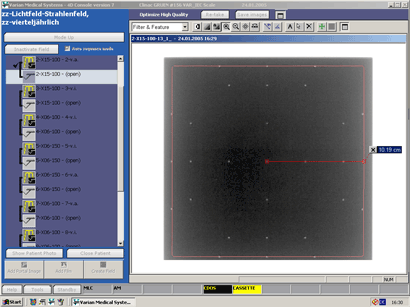 |
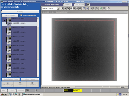
Fig.11: Usually a quick look confirms position and size of the radiation field, much faster than it is possible with radiographic film. |
Fig.12: This screenshot shows a quite large deviation of 1.9mm. |
 |
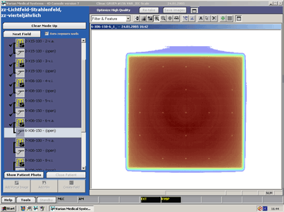 |
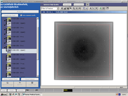
Fig.13: Some test fields require a SSD of 150cm. For this, the detector is moved to 183cm from focus, the maximum distance. |
Fig.14: The target field size is 13.3x13.3cm in this case. |
 |
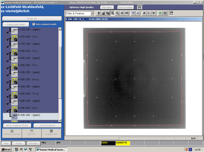 |
Fig.15: This image is acuired at Gantry 270° and Collimator 90°. |
Fig.16: All images are stored in the Vision database and can be reviewed offline. No more lost films. |