Fine-Tuning of the VERIQA Beam Model
During preliminary testing, all clinical plans had passed the GAM33 tests. However, the agreement between TPS (Eclipse18 AAA/AXB) and MC (SciMoCa™) dose was not yet perfect in the case of narrow DMLC gap fields. Some MC dose seemed to be missing for all energies.
In principle, the VERIQA user has two "knobs" for adjustments:
- Dose Calibration Correction (DCC)
- Leaf Offset Correction (LOC)
The DCC changes the Dose-per-MonitorUnit calibration of a beam model and is a global property. The LOC defines an offset between the nominal position of the leaves and the apparent position. If all leaf positions are shifted in highly modulated plans where gap openings are usually small, this can have a relevant impact on dose.
The VERIQA Configuration Protocol we received from PTW together with the beam models contains a table with recommended correction values for LOC and DCC:
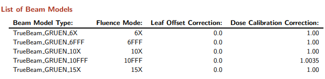
Only a small DCC of +0.35% was recommended for the 10FFF energy. We entered this value in the beam model settings accordingly.
Regarding LOC, no offset was given by PTW. However, when PTW created our customized beam models, they were not (yet) aware of Enhanced Leaf Modelling (ELM) in Eclipse version 18. While for PTW, the gap dose values are still the primary source of information during the MLC modelling process (which is good, because the measured values did not change with ELM), the additional role of the user-measured DLG values (which are now negative values due to the changed definition of DLG) in the MLC modelling process is not fully clear. We therefore simply took the LOC as an open dose fitting parameter.
The following shows the 10FFF beam model calibration in its final form:
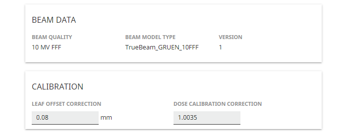
How did we determine the LOC for each energy (here: 8/100 mm)? Read on.
RT View
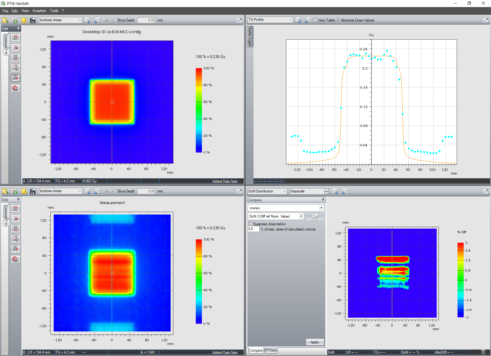
For dose profile comparisons, we installed the RT View software. As soon as an evaluation is finished in VERIQA, it can be forwarded to RT View, which loads the patient and starts the Plan Comparison. By checking one more box, RT View switches to the very useful Dose Profile Comparison:
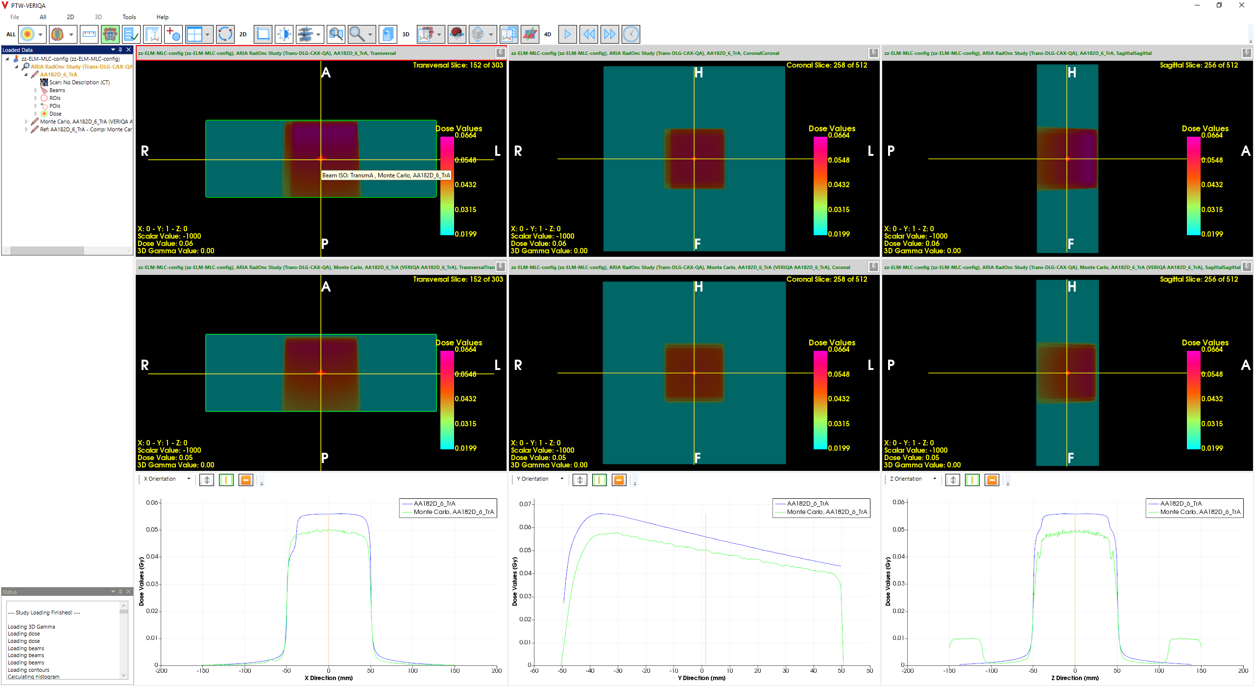
(Dose Profile Comparison in RT View. It took 11 min to calculate MC dose with a grid of 1 mm and 0.5% precision. The same "Open" field would take 5 min to calculate.)
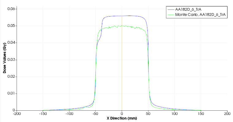
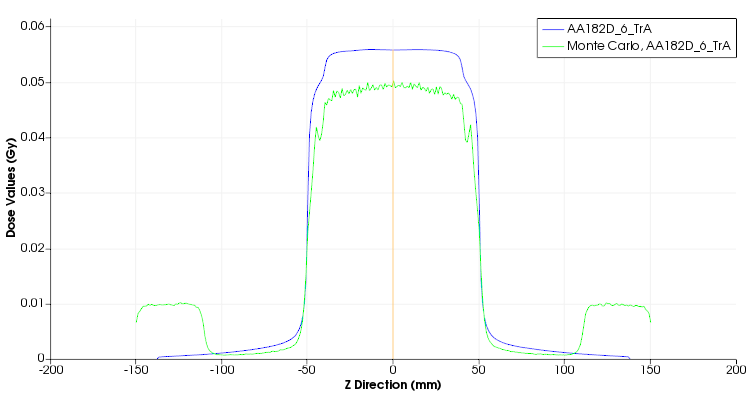
This RT View example above shows pure transmission dose through leaf bank A (TrA) for a 6X field on a water phantom. Although 500 MU are applied, AAA dose at isocenter (5 cm depth) is only 0.05 Gy (corresponding to a transmission value of roughly 1%). Upper row is AAA dose, middle row is MC. The profile comparison in the third row is very helpful for finding the best value for the LOC.
Note however that in the example shown, changing the LOC would not change MC dose. The situation is pure transmission. LOC adds a small offset to leaf positions, but the tip of all1 leaves is hidden under the X1 jaw!
The Gap Fields
The test plans that revealed the small dose discrepancy were the "Gap" fields which are also used during Eclipse commissioning.
(The Gap4 field. In reality, it is a continuous and smooth movement.)
The Gap4 field is a good candidate for optimizing LOC: a 4 mm wide moving MLC gap has enough sensitivity for small changes in leaf calibration. Wider gaps (6 mm or more) are less sensitive, while gaps that are too narrow may be problematic, because dose through a moving gap is the sum of the dose through the gap itself and the leaf transmission dose. During MC modeling, the transmission dose is treated separately by PTW based on the user given data. When the gap width is too small (e.g., 2 mm or less), the gap dose component decreases, which increases the relative contribution of transmission dose, because it remains constant.
As the Eclipse 3D dose distributions of the Gap4 fields already existed, they could be sent to VERIQA without modification. This started the optimization loop for LOC:
For each photon energy, do the following:
- Send calculated Gap4 plan to VERIQA
- Wait for VERIQA evaluation to finish
- Load evaluation to RT View
- Compare PDDs and profiles in RT View
- If MC dose is lower than TPS Dose:
- In VERIQA HOME > SETTINGS > DOSE CALCULATION > BEAM MODELS > energy: increase LEAF OFFSET CORRECTION and SAVE
- If MC dose is higher than TPS Dose:
- In VERIQA HOME > SETTINGS > DOSE CALCULATION > BEAM MODELS > energy: decrease LEAF OFFSET CORRECTION and SAVE
- Reevaluate the last evaluation (make sure the dose engine starts running2)
- Go to step 2.
After a few cycles, we found the optimal LOC values for our beam models.
All Eclipse and MC calculations were performed with 1 mm grid. The desired MC precision was 0.5%. The dose engine calculation time per field was about 7 minutes.
Results
The following values gave the best agreement at 5 cm depth.
LOC (6X) = 0.11 mm:
.png)
LOC (6FFF) = 0.10 mm:
.png)
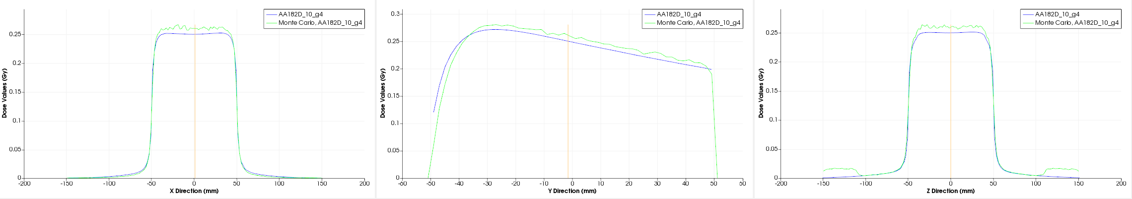
LOC (10X) = 0.08 mm:
.png)
LOC (10 FFF) = 0.08 mm:
.png)
LOC (15X) = 0.08 mm:
.png)
We determined the LOC values with AAA plans and checked them by repeating the evaluations for AXB. The agreement was practically the same.
Discussion
One should be aware that in the described process, we tried to minimize the dose discrepancy between TPS and MC, while ideally, the MC model should be compared to measurements, not TPS dose. However, detailed and reliable measurement results are hard to compile. The justification for the chosen approach is the following: if a TPS is thoroughly checked and accepted, it is OK to take the TPS as reference instead of measurements.
The fact that the VERIQA MC model is just one more model like AAA or AXB can be seen in the transmission example above, when we described RT View: on one hand, the MC model is not modelling correctly the full material at the frontmost 3 cm of each leaf tip: the blue X-profile (AAA) "knows" about this feature due to Enhanced Leaf Modelling. On the other hand, the green MC profile in Z-direction (inplane direction) correctly reproduces the two "bumps" that have the origin in the finite 22 cm length of the HD120 MLC. The same bumps also appear in the measurements (dots in cyan), but neither in AAA nor in AXB. In the former case, Eclipse "wins" over MC, in the latter case, MC wins over Eclipse. But all three (AAA, AXB, MC) are "only" models of reality ...
Since the first 100 evaluations had given no indication for systematic open field dose deviations, there was no need to touch the DCC (with the exception of the suggested 10 FFF correction already mentioned).
To give an idea of how sensitive Gap4 dose is to changes in LOC, here is the Profile Comparison for the 10X Gap4 field calculated with a LOC of 0.18 mm instead of the final 0.08 mm. MC dose (green) is clearly too high:
With the established LOC values, VERIQA is now ready for acceptance and commissioning.
Notes
1Not all leaves. To prevent the carriage of leaf bank A from following the A leaves, one leaf pair must be parked under the X2 jaw. Otherwise, the transmission measurement would give a wrong reading (too low).
2We noticed that if a reevaluation is initiated immediately after the LOC is changed in the settings, this will really only reevaluate the plan, with identical results. Another "Reevaluate" will do the job and get the dose engine running.