Measurements
of beam performance during IMRT
(Abstract for the
DGMP-Meeting in Passau, Germany, Sept. 15 - 18, 1999
The DGMP is the German Association
for Medical Physics)
H. Krauss,
S. Mitterer, A.U. Schratter-Sehn
Institute of Radiooncology, Kaiser-Franz-Josef Spital (KFJ), Kundratstraße 3,
A-1100 Vienna
harald.krauss@kfj.magwien.gv.at
Introduction
 Before Intensity Modulated Radiotherapy
(IMRT) can be introduced into clinical routine, the physicist has to verify,
among many other things, the beam performance during such dynamic treatment
techniques. During treatments of intensity modulated beams with Dynamic Multileaf
Collimators (DMLC, sliding window technique), the servo control of the Linac
may, under certain circumstances, lead to sharp variations of dose rate during
the whole treatment. Therefore, beam characteristics (mainly beam symmetry)
have to be verified not only during the startup phase of the Linac, but for
the entire treatment.
Material and Methods
With our two linear accelerators
(Varian Clinac 2300C/D) it is possible to deliver DMLC treatments in Clinical
mode, with full verification by the VARiS verification system. After treatment
planning with the Cadplan extension Helios ("inverse planning") all
treatment parameters including the DMLC file are exported to the VARiS system
and can be treated on both machines.
A static MLC file is a text
file that contains a single shape, whereas the dynamic MLC file consists of
a sequence of up to 320 shapes, each with an associated dose fraction (values
between 0.000 and 1.000). During execution, the control system enforces a linear
path of all leaves within a segment, with different leaves generally travelling
at different speeds. Figure 1 shows snapshots of four out of 200 segments of
a prostate field, planned with Cadplan/Helios, together with the resulting fluency
distribution. The four segments have the corresponding dose fractions 0.2513,
0.4523, 0.5578 and 0.7437, respectively.
 As long as the required MLC motions
do not result in any of the leaves exceeding their maximum speed, the operator-selected
dose rate is used (in the range of 100 – 600 MU/min). Otherwise, the controller
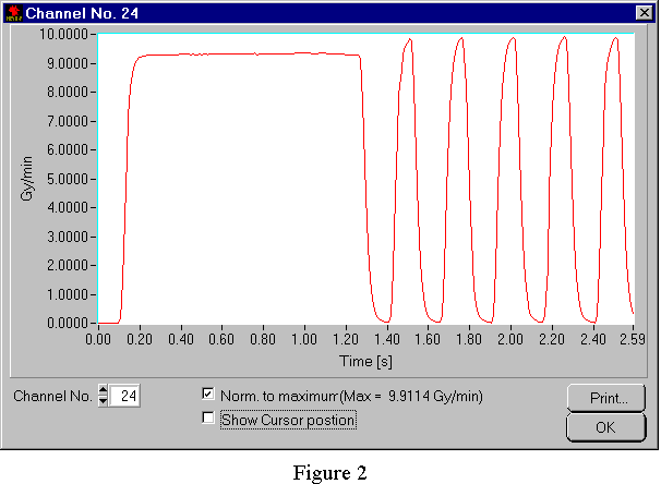
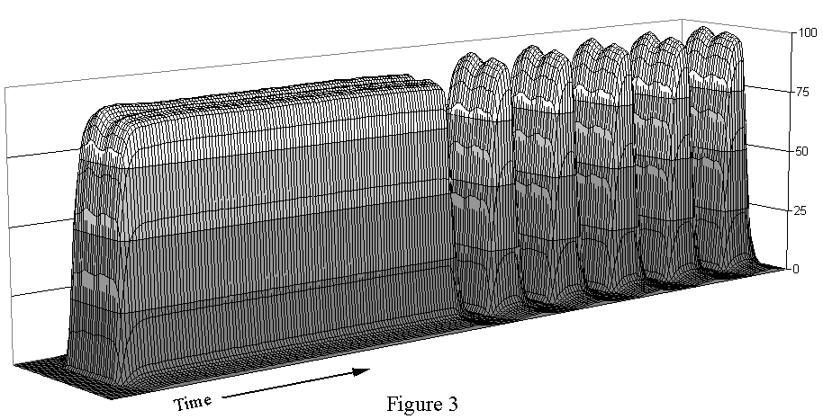
drops beam pulses, which leads to a sharp fluctuation of dose rate. Figure 2
shows the central axis dose rate for a DMLC test treatment, where leaves move
faster and faster until, after 1.2 seconds of beam, the maximum leaf speed is
reached. The array was positioned inplane at SSD = 70 cm and 10 cm depth in
water. Figure 3 shows the relative dose rate distribution in 3D, normalized
to 100% at dose rate maximum.
The sharp fluctuations pose
no problem a priori, as long as the beam characteristics are acceptable under
these conditions. The influence on total treatment time is moderate: the measured
treatment time of the field shown in Fig. 1 was 15 seconds (84MU @ 600 MU/min).
The time to position the patient on the couch would still be considerable longer
than the pure beam-on time. Therefore a complete IMRT/DMLC-treatment can be
delivered in about the same time as a "conventional" conformal treatment
with the same number of fields.

With our fast measuring
system (PTW Linear Array LA48, fast measurement option) it is possible to acquire
full beam profiles within 2 milliseconds and a repetition time of 10 ms [1].
With this system, the time dependence of dose rate and symmetry during DMLC
treatments were studied.
Results and Discussion
The measuring system has
a high time resolution. Within 2.5 s, 250 profiles can be measured and stored.
Analysis of symmetry was done with a commercial spread sheet program, using
the IEC 976 definition of symmetry. But one has to be careful with the analysis,
because on Linacs with a short beam rise time, an effect of the measuring system
can be observed that slightly distorts the results. The curve shown in Fig.
2 and 3 has a maximum change of dose rate ("dose acceleration") of
4 Gy/s2. Since the 47 ionisation chambers of the LA48 are read out
sequentially within 2 ms, this leads to a delay of 43 microseconds per channel
and can lead to a maximum error of the dose rate value of 5% for channel 47,
if the full field is used. By rotating the array by 180°, it can be shown that
the effect originates from the measuring system, not from the Linac. To find
the "true" symmetry, the raw data has to be corrected numerically.
Corrections of first order were made and showed that the symmetry is in the
range of the "static" values (see poster for details).
[1] St. Rassow, J. Moog,
M. Buchgeister, E. Schüle, F. Nüsslin, Profilmessungen in 10 ms-Intervallen
mit einem Linear-Array, in: Medizinische Physik 1998, Hrsg. L. Voigtmann und
P. Geyer, S. 99f
 Before Intensity Modulated Radiotherapy
(IMRT) can be introduced into clinical routine, the physicist has to verify,
among many other things, the beam performance during such dynamic treatment
techniques. During treatments of intensity modulated beams with Dynamic Multileaf
Collimators (DMLC, sliding window technique), the servo control of the Linac
may, under certain circumstances, lead to sharp variations of dose rate during
the whole treatment. Therefore, beam characteristics (mainly beam symmetry)
have to be verified not only during the startup phase of the Linac, but for
the entire treatment.
  As long as the required MLC motions
do not result in any of the leaves exceeding their maximum speed, the operator-selected
dose rate is used (in the range of 100 – 600 MU/min). Otherwise, the controller
drops beam pulses, which leads to a sharp fluctuation of dose rate. Figure 2
shows the central axis dose rate for a DMLC test treatment, where leaves move
faster and faster until, after 1.2 seconds of beam, the maximum leaf speed is
reached. The array was positioned inplane at SSD = 70 cm and 10 cm depth in
water. Figure 3 shows the relative dose rate distribution in 3D, normalized
to 100% at dose rate maximum.